Table of Contents
Advertisement
Quick Links
Advertisement
Table of Contents

Related Manuals for sauermann MP 210


Summary of Contents for sauermann MP 210
- Page 1 USER MANUAL THERMO-ANEMO-MANOMETER...
- Page 4 Battery level Date and time Measurement menu Dataset menu Information menu Configuration menu Home screen Function keys OK button Navigation arrows ESC button On/Off button ➢ Left key: allows to navigate from left to right ➢ Right key: allows to navigate from right to left ➢...
- Page 5 ➢ ➢ ➢ PRESENTATION...
-
Page 6: Connections Of The Mp 210
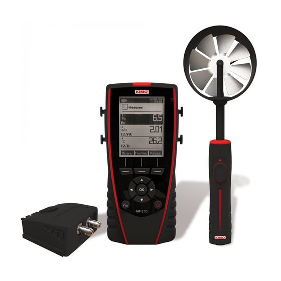
2. CONNECTIONS OF THE MP 210 • Screen • Printer (available as option) • Battery Interchangeable modules • Thermocouple module: CONNECTIONS OF THE MP 210... - Page 7 Pitot tube Debimo blades. • Wire probes with SMART-2014 system • Wireless probe / instrument communication Wireless probes shall be located near the instrument for initial recognition. Connection between MP 210 and wireless probes must be established. CONNECTIONS OF THE MP 210...
- Page 8 “Information” “Wireless probe” “Mini-DIN 1” “Mini-DIN 2” “Module” “Information” Available information for probes and module is: • • • • • Available information for the instrument is: • • • ➢ “Measurement” “Measurement” INFORMATION...
-
Page 9: Set The Instrument
➢ “Configuration” ➢ “Configuration” “Language” ➢ ➢ ➢ Press OK. ➢ “Configuration” ➢ “Date/time” ➢ “Date” ➢ ➢ ➢ ➢ ➢ “Time” ➢ “12H” “4H” “12H” “PM” ➢ “AM” “PM” ➢ ➢ ➢ ➢ “Validate” “Configuration” ➢ “Key beep” ➢ “Configuration”... - Page 10 “Configuration” ➢ 1 and 9 “Auto” ➢ ➢ “Configuration” ➢ “Security” ➢ “Configuration” ➢ Go to “Code” ➢ “Configuration” “Configuration” ➢ “Printing” ➢ “Format” ➢ Long ticket format: Short ticket format: “Logo” ➢ “Operator” ➢ ➢ “Delete” ➢ “Header 1” ➢...
-
Page 11: Set The Probes
• Connect a probe ➢ ➢ Instrument connection Probe connection ➢ “Measurement” ➢ Sensitive element (velocity) Sensitive element (temperature) Airflow direction Bottom of the telescopic probe Protective tube of the sensitive element (1) landmark Bottom of the standard probe Before any use of the device with an air velocity probe, please lower the protective tube (1) of the sensitive element (except vane probe). -
Page 12: Channel Configuration
Add a wireless probe • “Information” “Information” “Wireless probe” “Create” “Meas.” “Delete” “Measurement” “Add wireless probe...” “Measurements” “Probes”. “Channels” ➢ “Measurement” “Meas.” “Create” ➢ ➢ “Channels” “Delete” “Channels” CHANNEL CONFIGURATION... - Page 13 ➢ “Delete” ➢ “Add” ➢ “Add” “Channels” ➢ ➢ “Channel num.” Airflow: “channels” ➢ “Airflow” ➢ “Channel num.” ➢ ➢ “Type” ➢ “Rect”, “Circ” “K factor” OK*. K factor: Δ √ Qv=K× ΔP “Cone” “Rect” “Circ” “Cone” Cone” ➢ • : K35 K75 K120 K150 •...
- Page 14 ➢ “K2 fact.” Air velocity: “channels” ➢ “Air velocity” ➢ “Channel num.” ➢ “D/p pressure” D/p coeff.” ➢ “D/p pressure” ➢ ➢ “Channel” “channels” ➢ “Airflow” ➢ “Channel num.” ➢ ➢ “Type” ➢ “Rect”, “Circ” “K factor”* OK*. Rect Circ: ➢...
- Page 15 ➢ “Channels” “Delta T” ➢ “Channel number” ➢ ➢ ➢ “Channel A” ➢ ➢ ➢ “Channel B” ➢ ➢ “Measurement” CHANNEL CONFIGURATION...
- Page 16 ➢ “Measurement” ➢ ➢ ➢ “Functions” “Dataset” ➢ Name” ➢ ➢ “Delete” ➢ ➢ ➢ ➢ “Type” ➢ “Manu.” “Auto.” ➢ “Start” manual dataset ➢ ➢ ➢ “Save” ➢ ➢ “Zoom+” ➢ ➢ “Print” ➢ “Channels info” ➢ “Details” ➢ “Validate”...
- Page 17 ➢ ➢ “Validate” ➢ “Interval” ➢ “min” ➢ ➢ “Validate” ➢ ➢ “Start” • “Stop” • Start” • “Duration” • “Save” ➢ ➢ “Zoom+” ➢ ➢ “Print” “Channels info” ➢ “Details” ➢ “Validate” ➢ “Measurement” ➢ ➢ “Dataset” ➢ “Del all” ➢...
- Page 18 ➢ “Delete” ➢ “Validate” ➢ “Zoom+” ➢ ➢ “Print” ➢ “Channels info” ➢ ➢ “Details” ➢ “Validate” ➢ “Measurement” “Automatic” Averages” ➢ “Start” ➢ “Stop” ➢ ➢ “Start” ➢ “Save” ➢ ➢ “Delete” ➢ “Validate” ➢ “Zoom+” ➢ ➢ “Print” ➢...
- Page 19 ➢ “Duration” ➢ “min” ➢ ➢ “Validate” ➢ ➢ ➢ “Details” ➢ Save” ➢ ➢ “Delete” ➢ “Validate” ➢ ➢ “Zoom+” ➢ ➢ “Print” “Channels info” ➢ “Details” ➢ “Validate” ➢ “Measurement” ➢ ➢ “Functions” “COmax” ➢ “Duration” ➢ “min” ➢...
-
Page 20: Setting Of Measurement Parameters
“Measurement” ➢ ➢ “Params” ➢ ➢ “Channels” ➢ “Channel num.” ➢ ➢ “Pressure” ➢ ➢ ➢ “Temperature” ➢ ➢ ➢ “Airflow” ➢ ➢ ➢ “Air velocity” ➢ ➢ ➢ Select “Type Tc” ➢ ➢ Airflow: ➢ “Normo values” ➢ None DIN1343 ISO2533 SETTING OF MEASUREMENT PARAMETERS... - Page 21 “Temp.alarm” ➢ ➢ “High alarm” “Low alarm” ➢ “High threshold” ➢ ➢ “Low threshold” ➢ “Integration” ➢ 0 and 9 ➢ ➢ Press OK to validate. “Atmo. Press.” ➢ ➢ ➢ ➢ Temp.Comp” ➢ ➢ “Temperature” ➢ ➢ ➢ ➢ “Type Tc”...
- Page 22 ➢ “Air velocity” ➢ ➢ ➢ “Temperature” ➢ ➢ ➢ “Airflow” ➢ ➢ Integration “Integration” ➢ 0 and 9 ➢ ➢ ➢ “Normo Values” ➢ None, DIN1343 or ISO2533 ➢ “Temp.alarm” ➢ “High alarm” “Low alarm” ➢ “High threshold” ➢ ➢...
- Page 23 ➢ “Temperature” ➢ ➢ ➢ CO Alarm CO” “CO2 Alarm” ➢ “Alarm 1” “Alarm 2” ➢ “Threshold 1 ➢ ➢ “Threshold 2 ➢ ➢ “Temp. alarm” ➢ “High alarm” “Low alarm” ➢ “High threshold” ➢ ➢ “Low threshold” ➢ Tachometry” ➢...
- Page 24 www.sauermanngroup.com...
Need help?
Do you have a question about the MP 210 and is the answer not in the manual?
Questions and answers