sauermann Si-CA 230 User Manual
Gas analyser
Hide thumbs
Also See for Si-CA 230:
- User manual (20 pages) ,
- Quick start manual (32 pages) ,
- User manual (43 pages)
Table of Contents
Advertisement
Quick Links
Advertisement
Table of Contents

Related Manuals for sauermann Si-CA 230


Summary of Contents for sauermann Si-CA 230
- Page 1 USER MANUAL Si-CA 230 GAS ANALYSER www.sauermanngroup.com...
-
Page 3: Table Of Contents
Table of contents 1. Safety instructions ..............................5 1.1 Warnings ................................5 1.2 Environment protection ............................ 5 1.3 Symbols used ..............................5 2. Introduction ................................6 2.1 Analyser description ............................6 2.2 Main features ..............................7 3. First Start-up ................................ 10 4. - Page 4 10.1 Set the printer connection ..........................27 10.2 Custom the printing header .......................... 27 10.3 Set the number of copies ..........................27 11. Analyser information ............................28 11.1 Service and Calibration ..........................28 11.1.1 Calibration information ......................... 28 11.1.2 Service center contact ........................... 28 11.1.3 Perform calibration ..........................
-
Page 5: Safety Instructions
Send back the device at its end of working life to a waste collection center for electrical and electronic components (ac- cording to local regulations), or send it back to Sauermann to ensure a required waste collection in the respect of the environment. -
Page 6: Introduction
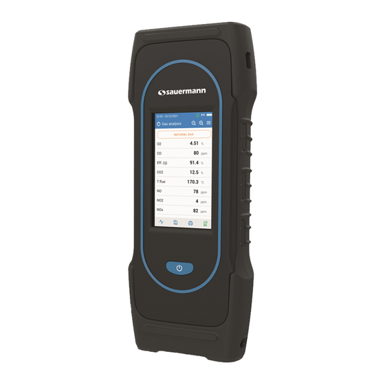
2. Introduction 2.1 Analyser description The Si-CA 230 is a flue gas analyser for emissions monitoring of boiler, engine, & other combustion applications with between two and six interchangeable gas sensors. Its main features are the following : • Gas sensor options include O... -
Page 7: Main Features
2.2 Main features • Screen Colour touch screen, 10.9 cm (4.3’’), 480 x 272 pixels with backlight. It allows to display measured parameters in a more comfortable format for the operator. Thanks to the zoom function, you can view on the screen the measured values in increased or decreased characters. - Page 8 BS 7967:2015, BS EN 50543:2011, UNE 60670-10 and ES.02173.ES Hereby, Sauermann Industrie SAS declares that the radio equipment type Si-CA 230 is in compliance with Directive 2014/53/EU. The full text of the EU declaration of conformity is available at the following internet address: www.sauermanngroup.com...
- Page 9 • Loss (Q+): Stack Heat Losses (gross) • CE (ηc): Condensation efficiency calculated acc. to the UNI 10389-1 standard • X Air: Calculated excess air • Lambda: Calculated lambda value (for air to fuel ratio) • Air Ind (n): Calculated air index •...
-
Page 10: First Start-Up
3. First Start-up When the analyser is first started up, parameters of the analyser must be set. Keep pressed for 3 seconds to turn ON the analyser. DO NOT insert the gas probe in the flue/chimney/stack at this time. Tap "Start". Select your Set the date language then tap... -
Page 11: Features
4. Features 4.1 General features Dimensions 28 x 11.2 x 5.5 cm (11 x 4.3 x 2’’) Weight 825 g (30 oz) Display Colour Touch Screen with Graphing; Size: 480 x 272 pixels Keypad 1 On-Off key Material ABS-PC Protection IP42 - Wireless: class 2 range, range frequency from 2402 MHz to 2480 MHz with a transmit power of 1 dBm. -
Page 12: Parameter Specifications
4.3 Parameter specifications Parameter Sensor Measuring range Resolution Accuracy Response time Electrochemical 0 to 25% 0.01% ±0.2% vol < 30 s ±8 ppm < 160 ppm CO (H comp.) Electrochemical 0 to 10,000 ppm 1 ppm ±5% rdg up to 2000 ppm <... -
Page 13: Perform A Flue Gas Analysis
OFF. In case of any default or damage of the instrument, Sauermann After-sales service shall be contacted. On the back of the analyser, there is a label with the analyser serial number. This number shall be communicated for every operation (technical operation or request of spare parts). -
Page 14: Perform A Draft Measurement With The Draft Probe
5.3.2 Perform a draft measurement with the draft probe The draft measurment can be performed thanks to the draft probe avalaible as option. If the draft probe is used, it will be necessary to drill another hole dedicated to this draft meas- urement in the duct. -
Page 15: Use The Zoom Function
5.8 Use the Zoom function From the gas analysis screen, the zoom function is available using The initial screen displays 8 measured values. • To zoom in, tap The screen displays 4 values. • To zoom in again, tap The screen displays 2 values. •... -
Page 16: Set The General Parameters Of The Analyser
6. Set the general parameters of the analyser The settings menu allows to set the general parameters of the analyser: • Time • Time zone • Date • Language • Country • Wireless connection • Autozero • Purge time • Brightness Any changes made to settings are automatically saved when you exit the screen. -
Page 17: Set The Brightness Of The Screen
6.8 Set the brightness of the screen “Settings > General” screen is displayed. • Tap “Brightness”. • Set the brightness level from 1 to 5. Set the general parameters of the analyser... -
Page 18: Set The Parameters Of The Analysis
7. Set the parameters of the analysis This menu allows to set the following itemes regarding the analysis: • Fuel • Alarms • CO dilution mode • Pump after autozero • CO dilution threshold • Zero draft sensor • CO pump cut-off level •... -
Page 19: Create A Fuel
• Tap "Save". The customized fuel is then integrated at the end of the fuel list. If a very specific fuel must be created please contact the Sauermann Service Center for further information. A customized fuel can be deleted: • Tap the name of the customized fuel on the fuel list. -
Page 20: Set The Co Pump Cut-Off Level
• Tap "CO dilution threshold". • Enter the required threshold between 100 and 4000 ppm. 7.4 Set the CO pump cut-off level This part allows to define the CO pump cut-off level. “Settings > Analysis” screen is displayed. • Tap “CO pump cut-off level”. •... -
Page 21: Set The Nox Factor
7.6 Set the NOx factor This part allows to set the NOx factor, which is the assumed NO to NO ratio used to calculate NOx when the NO sensor is included but the NO is not included. The same applies when NO and NO are low range sensors. -
Page 22: Zero Draft Sensor
Alarms can be revised later (for example, different threshold value) if needed. During the measurements, an alarm remains ON even if the measurement goes below or above the threshold value until it is acknowledged. If the alarm is acknowledged and the value is always in alarm, the alarm remains ON. 7.9 Zero draft sensor This part allows to reset the draft sensor and the high accuracy sensor (if this optional sensor is installed on the analyser).. -
Page 23: Set The Air Temperature
7.11 Set the air temperature This part allows to set the air temperature for the incoming air into the combustion equipment if known. This value is obtained by three different ways: • by an external probe if this optional probe is connected •... -
Page 24: Set The Stack Cross-Sectional Area
7.13 Set the stack cross-sectional area This part allows to define surface of the stack cross-sectional area that will help to measure the stack gas velocity. “Settings > Analysis” screen is displayed. • Tap “Stack cross-sectional area”. • Enter the surface between 0 and 99,999 cm Set the parameters of the analysis... -
Page 25: Set The Measuring Unit
8. Set the measuring unit This part allows to define the measuring unit for each parameters measured or calculated by the analyser. The following unit is avalaible according to the parameter: • Temperature: °C, °F • Pressure: mbar, iwg (inches water gauge), mmwg, mmHg, Pa, hPa, kPa, psi •... -
Page 26: Set The Data Saving
9. Set the data saving This part allows to define the data saving mode: manual or data logger “Settings” screen is displayed. • Tap “Data saving”. • Select “Manual”: data will be manualy saved during measurement. • Select “Data logger”: data will be saved according to a specified time interval and duration. •... -
Page 27: Set The Printer
10. Set the printer This part allows to set the printer specifications: printer connection, custom header and number of copies. This printer is avalaible as option. 10.1 Set the printer connection “Settings > Printer” screen is displayed. • Turn on your wireless printer. •... -
Page 28: Analyser Information
11.1.2 Service center contact “Service / Calibration” screen is displayed. • Tap “Service Center Contact” to display the address of the Sauermann Service Center. 11.1.3 Perform calibration This screen allows the user to perform a calibration on a gas sensor. -
Page 29: Gas Sensor Information
• Output current (in units of micro amps) • Sensor life estimation: a four bar display is shown. When down to one bar, it is recommended to contact an authorized Sauermann service center 11.3 Other information Analyser information screen also gives the following information: •... -
Page 30: Perform Other Measurements
12. Perform other measurements The analyser can perform other measurements than a gas analysis: • CO monitor • Gas tightness test • Gas/pump flow rate • Heat exchanger integrity test • Stack gas velocity 12.1 Perform CO monitoring The CO monitoring is performed with the external CO probe (available as option) or with the internal CO sensor. •... - Page 31 If Preliminary test is selected: • Select the fuel: natural gas or LPG. • Read the gas pressure inside the pipe. • Tap “Start stabilization”. The analyser starts the stabilization. • Tap “Start test” once the stabilization is completed. At the end of the test, the analyser displays the following results: •...
-
Page 32: Gas Pump Flow Rate
12.3 Gas pump flow rate This screen shows the real-time measured flow rate of the gas passing through the analyser as performed by the main flue gas sampling pump. The pump of the analyser must be turn on. “Other measurements” screen is displayed. •... -
Page 33: Perform A Measurement Of Smoke/Opacity
• For proper calculations of volumetric flow rate and mass flow rate, enter correct stack cross-sectional (see chapter "7.13 Set the stack cross-sectional area" on page 24) 12.6 Perform a measurement of smoke/opacity It is possible to enter in the analyser from 1 to 3 smoke/opacity indexes performed thanks to smoke/opacity pump avail- able as option. -
Page 34: Maintenance Of The Analyser
To ensure the measurement accuracy, sensors have to be calibrated only in Assistance center qualified by Sauermann. Sensor Average life-time... -
Page 35: Replace Filter Inside The Water Trap
Sensors have very precise locations, see the following locations defined for each sensor: • O2 sensor must be in O position • CO-H2 sensor must be in CO position • NO or low NO sensor must be in 6 position •... -
Page 36: Replace The Internal Filter
13.4 Replace the internal filter The filter inside the analyser is recommended be changed once a year. • Remove the protective rubber holster. • Turn the analyser on its back side. • Open the analyser by removing 6 screws with cruciform (Philips) screwdriver. The back shell can then be lifted up. -
Page 37: Optional Accessories
14. Optional accessories The following accessories are available: Part number Description Illustration 27520 (NO) NO or Low NO sensor for NOx 27521 (Low NO) 27526 (NO or Low NO sensor 27527 (Low NO 27528 (SO or Low SO sensor 27529 (Low SO 27530 CxHy sensor 27531... -
Page 38: Spare Parts
15. Spare parts The following spare parts are available: Item number Description 27697 Bottom Shell Piece with Hose & Tc Connection Ports 27705 Rechargeable Battery Pack 27707 Dilution pump 27716 Main gas sampling pump 27718 Upper Shell Assembly 27719 Lower Shell Assembly, With magnets 27720 Gas analysis chamber 27721... - Page 39 Sauermann Industrie Sauermann Italia SA ZA Bernard Moulinet Via Golini 61/10 24700 Montpon 40024 Castel S.Pietro Terme (BO) France T. (+39)-051-6951033 T. +33 (0)5 53 80 85 00 F. (+39)-051-942254 services@sauermanngroup.com info.italy@sauermanngroup.com Sauermann Ibérica Sauermann NA C/Albert Einstein 33. 140 Fell Court, Ste. 302 Planta 3.
Need help?
Do you have a question about the Si-CA 230 and is the answer not in the manual?
Questions and answers