Applied Instruments XR-3 Operation Manual
Modular test instrument, ts2 dbs satellite meter module
Hide thumbs
Also See for XR-3:
- Operation manual (55 pages) ,
- Manual (21 pages) ,
- Application note (2 pages)

Related Manuals for Applied Instruments XR-3


Summary of Contents for Applied Instruments XR-3
- Page 1 XR-3 Modular Test Instrument TS2 DBS Satellite Meter Module Operation Manual Revision 1.00 Date 04/02/2015 PUCHASE THE TURBO-S2 MODULE FOR THE XR-3 TESCOM USA TESCOMUSA.COM...
-
Page 2: Table Of Contents
XR-3 TS2 Module Operation Manual XR-3 INTRODUCTION TO XR-3’S TS2 MODULE ................. 4 ............................. 5 ONNECTIONS RUN SCREEN ............................6 ..............................7 ..........................7 HANGING ATELLITES ........................7 HANGING RANSPONDERS ..............................7 ... - Page 3 SPECIFICATIONS ........................65 This manual covers basic operations and functions of the XR-3’s TS2 Module. For more detailed instructions on how to use the instrument for different applications, see the Application Notes available on our website, http://www.appliedin.com Page 3 of 66 TESCOM USA TESCOMUSA.COM...
-
Page 4: Introduction To Xr-3'S Ts2 Module
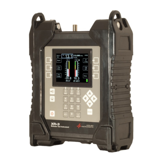
XR-3 TS2 Module Operation Manual XR-3 1. Introduction to XR-3’s TS2 Module The XR-3’s TS2 module is used with the XR-3 modular test instrument base unit. XR-TS2-01 tuner module XR-3 base unit FEATURES Compatible with XR-3 Modular Test Instrument ... -
Page 5: Connections
The XR-3 TS2 module represents a new standard in satellite identification capability. Rather than loading a limited set of satellites or a large number of channel plans to select from, the XR-3 TS2 module holds all of the compatible satellite transponder information for the entire continent. -
Page 6: Run Screen
XR-3 TS2 Module Operation Manual XR-3 Allows voltage supplied by IDU / IRD to power the LNB extending the battery life of meter However, the meter itself is always powered by its internal battery or by the external AC to DC switching power supply while connected to AC power. -
Page 7: Soft Keys
XR-3 TS2 Module Operation Manual XR-3 Soft Keys 1) SYST - transfers to the System Setup Screen 2) ID - starts satellite identification verification function 3) AZ/EL - transfers to the Azimuth and Elevation Lookup Screen 4) Polarity - displays or selects polarity and LNB voltage... -
Page 8: Multi-Lnb Systems
XR-3 TS2 Module Operation Manual XR-3 Multi-LNB Systems When the selected LNB system supports multiple LNBs or multi-head LNBFs via the switch setting, the LNB ON/OFF button also controls the switch setting. Upon pressing the LNB power soft-key, the meter sends a switch command to toggle to the next feed horn and the satellite is automatically changed to the one normally used for that port. -
Page 9: Satellite Identification
ID Verification Unlike other meters, the XR-3 has the ability to check one or more transponders looking for a match on a combination that is unique to each satellite. This is what we call the “ID Verification”... -
Page 10: Satellite Scan
If you have peaked up the signal level (left bar graph) on a satellite, but either don’t have a signal quality and lock or get an “ID FAILED” message when performing the ID Verification, the XR-3 can try to determine which satellite you are pointed at by performing the ID Verification on different satellites sequentially. - Page 11 XR-3 TS2 Module Operation Manual XR-3 Page 11 of 66 TESCOM USA TESCOMUSA.COM...
-
Page 12: Main Menu
XR-3 3. Main Menu The MENU button takes you to a menu of all of the XR-3 screens. Some of these screens are also available via soft keys from the Run Screen. All of the functions are available on the central menu using the up/down and Enter keys. Some functions are also available via soft keys as a shortcut. - Page 13 XR-3 TS2 Module Operation Manual XR-3 This screen is a simple menu selection. Use the up/down arrows to highlight the selection you want to change and press ENTER. The system selection actually selects three items: 1) Region 2) LNB system...
-
Page 14: Regions
(except for the Hawaii region, which is found in the NE Pacific Field Guide) loaded into it. If you are using the XR-3 outside of North America, you must download a different Field Guide from our website. See the Updating chapter for details. -
Page 15: Systems
XR-3 TS2 Module Operation Manual XR-3 Systems The system selection lets you pick the type of system within the selected service. In some cases this is the final LNB model selection. In other cases, the system will be broken down further by the LNB model selection. -
Page 16: Switch Type
When you connect the XR-3 to an external switch rather than directly to the LNB, or when you connect to a multi-LNB head, the XR-3 must know what switch type is connected so it can send the proper type of command to control that switch. -
Page 17: Options
XR-3 TS2 Module Operation Manual XR-3 5. Options There are several options you may select to personalize the operation of your meter. To use this screen, highlight the option you want to change with the up/down arrow keys and select the value you want with the left/right arrow keys. Press EXIT soft-key when done. -
Page 18: Shutdown Timer
If you select Freq Dev = YES, the lower left corner of the Run screen will display an estimate of the frequency deviation or drift of the LNB. The XR-3 is capable of locking onto a signal up to ... -
Page 19: Versions
Selecting Versions from the Main Menu list takes you to a screen that displays versions of software that are loaded in the instrument. It also displays the hardware versions and serial numbers of the XR-3 base unit and any connected module, as well as the active Field Guide and Postal Code and Limits files. -
Page 20: Azimuth / Elevation Lookup
XR-3 TS2 Module Operation Manual XR-3 7. Azimuth / Elevation Lookup The meter can look up the azimuth, elevation, and polarization offset for different satellites based on the latitude and longitude that you specify. The azimuth is given in true north (Azimuth) and in magnetic north (Magnetic) degrees. -
Page 21: Polarization Offset
XR-3 TS2 Module Operation Manual XR-3 The database titled ‘No Postal Code’ should be chosen if you are located outside of North America. This database allows you to type in and save your latitude and longitude coordinates and look up antenna settings based on those coordinates. Type in the latitude and longitude directly and press ENTER. -
Page 22: Manual Tuning
The parameter changes will be kept when you return to the Run Screen but not saved when powering off or changing to other satellites or transponders. If you need to permanently save a transponder to the XR-3’s database, then use the Custom Transponder feature. -
Page 23: Frequency
**TS2 module has limited compatibility with DIRECTV DVB-S2 signals and locks are not supported, but an estimated carrier to noise ratio is displayed. ***XR-3 will display only RF signal level (i.e. dBm) when tuned to a transponder with an incompatible signal type, but will not display lock or demodulated signal quality. -
Page 24: Options
XR-3 TS2 Module Operation Manual XR-3 Options Use the left/right arrow keys to toggle through the options related to your chosen signal type. If DVB-S2 signal type is selected and you have chosen a specific code rate, then you may choose between ‘Pilot on’... - Page 25 XR-3 TS2 Module Operation Manual XR-3 Any saved custom transponders in the meters database will be shown. If none have been saved, meter will indicate that. If you wish to edit those already saved custom transponders, highlight a custom transponder and press Enter button.
- Page 26 ID transponder for that satellite. ***Remember that the XR-3 satellite meter is only designed to measure the downlink / receive / outbound signal. Please do not enter any transponder parameters for the uplink / transmit / inbound signal, as the parameters will not be of any utility in the meter.
-
Page 27: Voltage / Current
- returns to the Main Menu Screen For the voltage, the XR-3 can output 13V, 18V, 21V for DIRECTV SWiM LNBs, or 29V. Note: In the screenshot shown above, approximately 18 volts is being output by the meter to the LNB. -
Page 28: Opi And Diseqc Monitoring
XR-3 TS2 Module Operation Manual XR-3 11. OPI and DiSEqC Monitoring The OPI/DiSEqC Screen serves two similar purposes. First, it simulates the Hughes OPI (Outdoor Pointing Interface) used to check cross-pol alignment of the HughesNet Ku Band transmitters. Second, it decodes and displays other DiSEqC commands received on the IDU / IRD port of the meter. -
Page 29: Diseqc Monitoring
PC to generate the display shown on the meter. 4) Return to the dish and connect the XR-3 into the receiver cable. The XR-3’s ODU / LNB port should be connected to the LNB and the IDU / IRD port to the modem’s Rx port. - Page 30 XR-3 TS2 Module Operation Manual XR-3 Pre-FEC The errors that are corrected by the first stage in the decode process, the Viterbi decoder, are displayed for DVB-S, DSS / DIRECTV Legacy, and Digicipher 2 signals. This rate is sometimes referred to as the “pre-FEC” error rate.
- Page 31 XR-3 TS2 Module Operation Manual XR-3 In most cases, a one minute test is sufficient to determine the BER for the present conditions. As long as both rates continue to read less than some number (the < character is shown), then no errors have been detected and the system is working well.
- Page 32 XR-3 TS2 Module Operation Manual XR-3 Code rate or bit puncture rate Data rate – calculated rate of payload kilo-bits per second (post-FEC data rate) Bit rate Elapsed time counter (seconds) Page 32 of 66 TESCOM USA TESCOMUSA.COM...
-
Page 33: Proof Of Performance Testing
The MeterMaid program is required to transfer the data from the instrument to the PC and to print reports. This software is available from the Applied Instruments website along with the FlashUpdate software used to upgrade the instrument. (See Updating section.) Collect Test Data Perform your satellite dish alignment as usual. -
Page 34: Saving Data
XR-3 TS2 Module Operation Manual XR-3 The meter will scan through all transponders on the satellite collecting the measurement data. You may press STOP to abort the scan, otherwise, wait until the scan completes. When the scan completes, the following screen displays a summary of the data: You press “EXIT”... - Page 35 XR-3 TS2 Module Operation Manual XR-3 A new key always moves to a new column. A pause will also move to a new column. Left/right keys move between columns. Again, press “NEXT” to continue and the next screen lets you enter a file name: The file name must be unique.
-
Page 36: Transfer Data File To Pc
2) Start MeterMaid after the meter has completed its 5 second boot-up countdown. An icon that looks like the XR-3 should be installed on your desktop for this purpose. 3) The File Transfer window appears somewhat like the following example. -
Page 37: Erasing Files
XR-3 TS2 Module Operation Manual XR-3 folders by double clicking on the folder icons shown in the destination file box. The [parent] folder icon takes you up one level. Select the files on the left that you want to transfer by clicking on them. Selected files are highlighted. - Page 38 XR-3 TS2 Module Operation Manual XR-3 The report itself may not fit entirely on the screen but you may scroll down to see the rest. It is recommended to right click with your mouse on the Proof of Performance Scan report and select Properties/Results Only before printing PoP Scans to reduce the number of columns printed.
- Page 39 XR-3 TS2 Module Operation Manual XR-3 Page 39 of 66 TESCOM USA TESCOMUSA.COM...
-
Page 40: Limit Scan
XR-3 14. Limit Scan The XR-3 Signal Level Meter includes a Limit Scan feature that performs a quick scan of up to 5 transponders on a satellite, checks the values against pre-determined limits, and provides a pass/fail indication. Use this test to quickly verify your installation against recommended level and quality values. -
Page 41: Scanning
XR-3 TS2 Module Operation Manual XR-3 Scanning Selecting “Limit Scan” from the Main Menu will start the Limit Scan screen. If limits have already been defined for the presently selected satellite, the scanning will start immediately. The Limit Scan is only useful if the LNB is being powered by the meter. Press the LNB soft-key (located near middle right area of screen) to power the LNB. -
Page 42: Editing Limits
XR-3 TS2 Module Operation Manual XR-3 c. All Above Avg – the measured IRD Signal Quality of all transponders tested is above the average limit and the measured Signal Level of all transponders is above the Signal Level limit. d. Some Below Avg – the measured IRD Signal Quality of at least one of the transponders tested is below the average limit and the measured Signal Level of all transponders is above the Signal Level limit. - Page 43 XR-3 TS2 Module Operation Manual XR-3 Press EDIT soft-key to define limits. Upon entering the Limit Scan’s edit screen, when a satellite with no limits is selected, the edit screen contains zeros for all transponders: You will see a small underline cursor on the field that may be modified. Use the up/down arrow keys to move cursor to next desired field when no editing is necessary.
-
Page 44: Preset Limits
XR-3 TS2 Module Operation Manual XR-3 To remove a transponder, enter zero for the transponder number. If all transponders have been zeroed for a satellite, that orbit will be removed from the Limit Scan table. You may also use the “TR#” soft-key to insert a valid transponder number from the list of transponders for that satellite from the meter’s database. - Page 45 IRD signal quality values and minimum Signal Level Limits (dBm) for each zip code to Applied Instruments. The preset limits for DISH are usable for most Dish Network satellites (61.5, 72.7, 77, 110, 118.7, 119, and 129).
-
Page 46: Errors
XR-3 TS2 Module Operation Manual XR-3 7) Press the EXIT soft-key to return to the main Limit Scan screen to begin running a Limit Scan. Errors If you enter an invalid transponder number, the error will be detected after you press DONE and the system tries to scan that channel. -
Page 47: Limitations
To accomplish this, you can save the Limit Scan to the flash memory of the XR-3 while out in the field. Then you can upload it to a PC when back at the office to store the documentation on your hard drive or forward it on to upper management if required. - Page 48 XR-3 TS2 Module Operation Manual XR-3 Then you must type in a unique file name for this Limit Scan. An error message will appear if you enter a name that has already been used. To determine which names have been used, you can run the MeterMaid program on a PC or can select ‘File Utility’...
-
Page 49: Install Pc Software & Transferring Data Files To Pc
XR-3 TS2 Module Operation Manual XR-3 Install PC Software & Transferring Data Files to PC The process for transferring the saved Limit Scans to your PC is identical to the process for transferring saved Proof of Performance scans. Please see the Proof of Performance Testing section of the operation manual for instructions of how to transfer the saved files to your PC using the MeterMaid application. - Page 50 XR-3 TS2 Module Operation Manual XR-3 Page 50 of 66 TESCOM USA TESCOMUSA.COM...
-
Page 51: Spectrum Screen
XR-3 TS2 Module Operation Manual XR-3 15. Spectrum Screen The spectrum screen may be used to: Look for the presence of carriers Look at a carrier with an incompatible modulation type or encryption Optimize your polarity adjustment (null out the opposite polarity) ... - Page 52 XR-3 TS2 Module Operation Manual XR-3 Cursor Position Press Up/Down arrow keys to move cursor line vertically to different amplitude levels on the y- axis. The level (Level) at the cursor position is shown in the bottom center area of the screen.
- Page 53 XR-3 TS2 Module Operation Manual XR-3 Spectrum screen after pressing LVL to perform auto level scaling: Resolution and Refresh Rate Press +/- key on numeric keypad to change the number of samples per sweep. You can choose between 80, 160, or 320. 80 samples results in lower resolution and less detail, but a faster sweep.
-
Page 54: Constellation
XR-3 TS2 Module Operation Manual XR-3 Spectrum Menu fields include: Save scan – allows you to save a screenshot of the screen as it appeared immediately before entering the Spectrum Menu for later recalling and viewing in the meter or on a PC ... - Page 55 XR-3 TS2 Module Operation Manual XR-3 Sample QPSK Constellation: Sample 8PSK Constellation: Soft-Keys: 1) Clear – clears the present constellation diagram (new diagram will begin to be plotted) 2) Exit – exits to Run screen Page 55 of 66 TESCOM USA...
-
Page 56: File Utility
XR-3 TS2 Module Operation Manual XR-3 17. File Utility The File Utility feature allows you to see the filenames that you have used for saved scans. You can also delete a single file or format the flash drive and therefore erase all saved files from the flash memory of the selected drive. - Page 57 XR-3 TS2 Module Operation Manual XR-3 To delete a single file, highlight the file using the up/down arrow keys and then press the Delete soft-key. Note that erasing a single file does not free up flash memory. You must use the Format function to really erase the files.
- Page 58 XR-3 TS2 Module Operation Manual XR-3 Page 58 of 66 TESCOM USA TESCOMUSA.COM...
-
Page 59: Updating Your Meter
Spectrum Scans = .SPC 18. Updating Your Meter Updates to the Field Guide and to the instrument firmware are available from the Applied Instruments website. See Software Updating section in XR-3 base operation manual for more information. Page 59 of 66 TESCOM USA TESCOMUSA.COM... -
Page 60: Power
During cold weather keep the XR-3 indoors in a warm environment while charging. The battery charge temperature range is 41°F to 100°F or 5°C to 38°C. -
Page 61: Ac Power
Ensure that you are using the proper LNB type and that you have specified the correct LNB type in the System Setup software menu. If in doubt, refer to the label or tag on the body of the LNB and contact Applied Instruments' Tech Support department to consult with them. - Page 62 No. The IRD/satellite receiver isn’t powerful enough to power both the meter and the LNB. When the IRD is hooked up to the IDU / IRD port of the XR-3’s TS2 module, it can power the LNB through the meter (if the ODU / LNB port of the meter is connected to the LNB).
- Page 63 If your company has a strict policy and the firewall blocks any executable files, then please contact your IT department and ask for assistance. Applied Instruments is more than happy to speak to the IT department about a work-around solution.
-
Page 64: Replacement Parts & Accessories
Battery door gasket for model XR-3 975-09340 Shoulder Strap 978-01843 Replacement Battery for model XR-3 742-00016 120-240VAC/15VDC AC Adapter and related line cord for model XR-3 990-08520 12VDC Vehicle Battery Charge Cord 967-20003 USB Data Transfer Cable 983-00002 Desktop kickstand for model XR-3... -
Page 65: Specifications
After the repair is completed, we will contact you for payment. If payment is not received within 60 days after contact is made, then the repaired equipment will become the property of Applied Instruments. Version Updating As our product lines are refined and features and performance are enhanced, we will upgrade older units at a nominal cost when possible. - Page 66 Any application recommendation made by Applied Instruments for the use of its products is based upon tests believed to be reliable, but Applied Instruments makes no guarantee of the results to be obtained. This warranty is in lieu of all other warranties, expressed or implied, and no representative or person is authorized to represent or assume for Applied Instruments any liability in connection with the sale of our products other than that set forth herein.
Need help?
Do you have a question about the XR-3 and is the answer not in the manual?
Questions and answers