Advertisement
—— Installation and Safe Use Manual ——
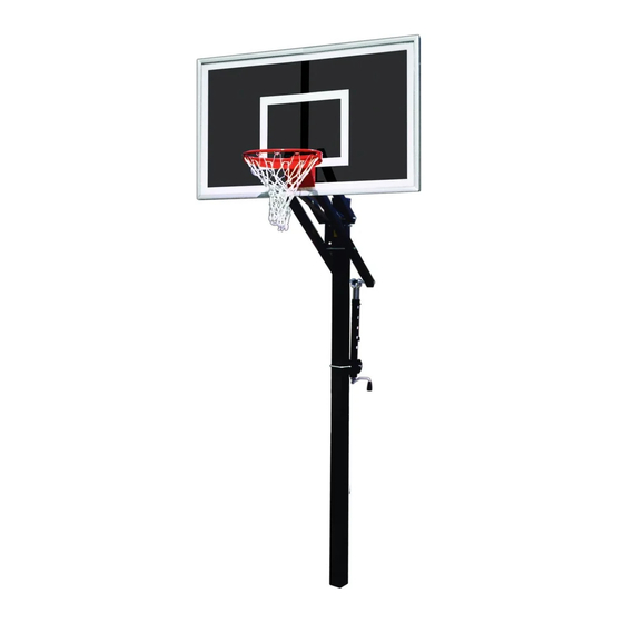
Qwik Change Basketball Systems
Model BA89QC-AW, BA89QC-BK
See Installation Video at www.youtube.com/bisoninc
P A R T S L I S T
Item
Qty Description
A
1
Extension Arm Assembly
B
2
4" Square U-Bolt
C
4
1/2" Flat Washers
D
4
1/2" Lock Washers
E
4
1/2" Hex Nuts
F
2
Upper Backboard Supports
G
2
Lower Backboard Supports
H
4
Backboard Mounting Angles
I
8
5/16" x 1" Hex Bolts
Improper installation, maintenance or use may cause product failure and serious personal injury.
Inspect all contents prior to installation. Report any missing parts to dealer immediately.
Carefully read all instructions before proceeding. Pay special attention to the safety instructions on page 4.
Save this instruction in the event that the manufacture must be contacted in the future for maintenance information.
1. Call your local utility locating service before digging, usually by dialing 811, to avoid serious injury or
service interruptions. Also avoid lawn sprinkler lines.
2. Determine the desired position of the 4" Square Pole (O) by taking into consideration that the distance
between the front of the 4" Square Pole (O) and the face of the Acrylic Backboard (L) changes as the
Rim (N) height is adjusted. At the top position (official 10' height) the distance is 22 1/2", at the lowest
position the distance is 28" and at middle heights the distance is 30" to 31". See Figure 1.
3. Dig a minimum 8" diameter footing at least 36" deep, deeper in heavy frost areas. Remove dirt in the
bottom 1/3 of the hole in a bell shape to improve pole stability. Amount of Quick Dry Cement (Q) required
will depend on final size of hole but an 8" hole, 36" deep with minor soil removal from the bottom will
require approximately 1.25 cubic ft. of premixed concrete. Always better to have too much rather than
too little on site. See Figure 1.
4. Fill the footing to the top with medium wet, fully mixed concrete. Never use the Quick Dry Concrete (Q)
dry.
5. Install the Pole Installation Aid Kit (P) around the 4" Square Pole (O) using the instructions provided
with the Pole Installation Aid Kit (P) inside the 4" Square Pole (O). See Figure 1.
6. Insert the 4" Square Pole (O) into the center of the footing making sure that the warning label is at the
back side of the 4" Square Pole (O) and that the flat front face of the 4" Square Pole (O) is square
to the playing surface. If your warning label becomes damaged or unreadable, request a no cost
replacement from the manufacturer. See Figure 1.
Date: 07/07/21
Rev: 13
Warning!
N.J.C.
Item
Qty
Description
J
8
5/16" Flange Nuts
K
1
Pole Cap
L
1
Acrylic Backboard (packaged separately)
M
1
Acrylic Hardware (packaged with backboard)
N
1
Rim and Net (packaged separately)
O
1
4" Square Pole (packaged separately)
P
1
Pole Installation Aid Kit (inside the pole)
Q
TBD Quick Dry concrete (provided by customer)
R
1
Pole Pad (packaged separately)
File: BA89QC-BK.pub
Customer Service
(800) 247 7668
Ref#: 920096
Advertisement
Table of Contents

Subscribe to Our Youtube Channel
Related Manuals for Bison BA89QC-AW


Summary of Contents for Bison BA89QC-AW
- Page 1 —— Installation and Safe Use Manual —— Qwik Change Basketball Systems Model BA89QC-AW, BA89QC-BK Customer Service See Installation Video at www.youtube.com/bisoninc (800) 247 7668 P A R T S L I S T Item Qty Description Item Description Extension Arm Assembly 5/16"...
- Page 2 RIM HEIGHT DIM “X” 10’ 22.5” 9’ 30” 8’ 31” 7 1/2’ 28” Warning Label 110" Minimum Figure 2 36" Reference Figure 1 8" Minimum 7. While the concrete is still wet and the 4" Square Pole (O) is movable, adjust the Pole Installation Aid Kit (P) on the 4"...
- Page 3 Figure 4 Figure 3 13. Using two 4" Square U-Bolts (B), four 1/2" Flat Washers (C), four 1/2" Lock Washers (D), and four 1/2" Hex Nuts (E) mount the Extension Arm Assembly (A) loosely to the front of the 4" Square Pole (O) at eye level or higher from a ladder or bed of a pickup.
- Page 4 TO RAISE GOAL: Place the end of a suitable lifting pole (I.E. broom handle) under the rim or backboard and push upward until desired height is reached. The mechanism will automatically lock in one of the fixed adjustment positions as unit is lowered slightly. See Figure 5. TO LOWER GOAL: Place pole into the black release cup of the ad- justment mechanism, push upward to release, then lower the goal to the lowest position.
Need help?
Do you have a question about the BA89QC-AW and is the answer not in the manual?
Questions and answers