PaloAlto Networks PA-400 Series Hardware Reference Manual
Next-gen firewall
Hide thumbs
Also See for PA-400 Series:
- Hardware reference manual (68 pages) ,
- Quick start manual (2 pages) ,
- Hardware reference manual (60 pages)
Table of Contents
Advertisement
Quick Links
- 1 Pa-400 Series Front Panel
- 2 Install the Pa-400 Series Firewall on a Flat Surface
- 3 Install the Pa-400 Series Firewall in a 19-Inch Equipment Rack
- 4 Install the Pa-400 Series Firewall Using the Pan-Pa-400-Racktray
- 5 Set up a ConnecOn to the Firewall
- 6 Service the Pa-400 Series Firewall Hardware
- 7 Interpret the Leds on a Pa-400 Series Firewall
- 8 Physical SpecificaOns
- Download this manual
Advertisement
Table of Contents

Related Manuals for PaloAlto Networks PA-400 Series


Summary of Contents for PaloAlto Networks PA-400 Series
- Page 1 PA-400 Series Next-Gen Firewall Hardware Reference docs.paloaltonetworks.com...
- Page 2 Alto Networks. A list of our trademarks can be found at www.paloaltonetworks.com/company/ trademarks.html. All other marks menoned herein may be trademarks of their respecve companies. Last Revised November 16, 2021 PA-400 Series Next-Gen Firewall Hardware Reference 2021 Palo Alto Networks, Inc. ©...
-
Page 3: Table Of Contents
Install the PA-400 Series Firewall on a Flat Surface............22 Install the PA-400 Series Firewall on a Wall..............24 Install the PA-400 Series Firewall in a 19-inch Equipment Rack........29 Install the PA-400 Series Firewall Using the PAN-PA-400-RACKTRAY... 29 Set Up a Connecon to the Firewall..................35 Connect Power to a PA-400 Series Firewall.......... - Page 4 Table of Contents PA-400 Series Next-Gen Firewall Hardware Reference 2021 Palo Alto Networks, Inc. ©...
-
Page 5: Before You Begin
Before You Begin Read the following topics before you install or service a Palo Alto Networks next- ® generaon firewall or appliance. The following topics apply to all Palo Alto Networks firewalls and appliances except where noted. > Upgrade/Downgrade Consideraons for Firewalls and Appliances >... -
Page 6: Upgrade/Downgrade ConsideraOns For Firewalls And Appliances
If the value the downgrade. If the is less than 20, then value is less than 20, contact support for then contact support for assistance. assistance. PA-400 Series Next-Gen Firewall Hardware Reference 2021 Palo Alto Networks, Inc. ©... -
Page 7: Tamper Proof Statement
• The integrity of the warranty label on the firewall or appliance is not compromised. (PA-7000 Series firewalls only) PA-7000 Series firewalls are modular systems and therefore do not include a warranty label on the firewall. PA-400 Series Next-Gen Firewall Hardware Reference 2021 Palo Alto Networks, Inc. ©... -
Page 8: Third-Party Component Support
Before You Begin Third-Party Component Support Before you consider installing third-party hardware, read the Palo Alto Networks Third-Party Component Support statement. PA-400 Series Next-Gen Firewall Hardware Reference 2021 Palo Alto Networks, Inc. ©... -
Page 9: Product Safety Warnings
• I/O ports are intended for intra-building connecons only and not intended for OSP (Outside Plant) connecons or any network connecons subject to external voltage surge events. PA-400 Series Next-Gen Firewall Hardware Reference 2021 Palo Alto Networks, Inc. ©... - Page 10 Toutefois, vous devez le faire dans les 45 secondes et vous ne pouvez remplacer qu’un roir à la fois, sinon le circuit de protecon thermique arrêtera le pare-feu. PA-400 Series Next-Gen Firewall Hardware Reference 2021 Palo Alto Networks, Inc. ©...
- Page 11 (de service) qu'à l'aide d'un oul spécial, cadenas ou clé, ou autre disposif de sécurité, et qui est contrôlée par l'autorité responsable du site. PA-400 Series Next-Gen Firewall Hardware Reference 2021 Palo Alto Networks, Inc. ©...
- Page 12 • A suitably-rated DC mains disconnect device must be provided as part of the building installaon. French Translaon: Un interrupteur d'isolement suffisant doit être fourni pendant l'installaon du bâment. PA-400 Series Next-Gen Firewall Hardware Reference 2021 Palo Alto Networks, Inc. ©...
-
Page 13: Pa-400 Series Firewall Overview
® 10.1 First Supported Soware Release for the PA-410: PAN-OS 10.1.2 ® The following topics describe the hardware features of the PA-400 Series firewall. To view or compare performance and capacity informaon, refer to the Product Selecon tool. > PA-400 Series Front Panel >... -
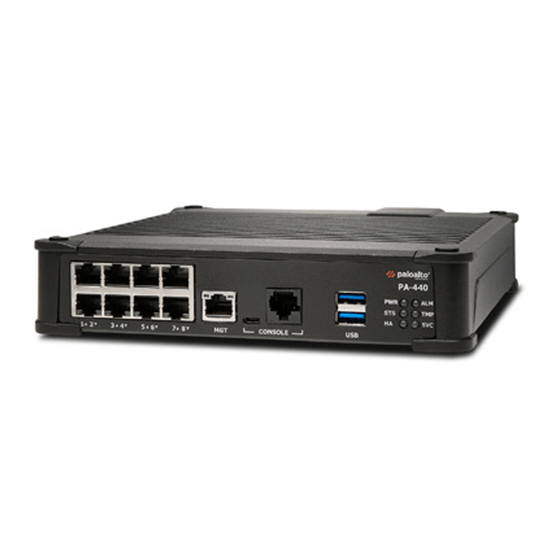
Page 14: Pa-400 Series Front Panel
(Micro USB) firewall using a standard Type- A USB-to-micro USB cable. The console connecon provides access to firewall boot messages, the Maintenance Recovery Tool PA-400 Series Next-Gen Firewall Hardware Reference 2021 Palo Alto Networks, Inc. ©... - Page 15 • Stop bits: 1 • Flow control: None USB port Use this port to bootstrap the firewall. Bootstrapping enables you to provision the firewall with a specific PAN-OS configuraon PA-400 Series Next-Gen Firewall Hardware Reference 2021 Palo Alto Networks, Inc. ©...
- Page 16 LED status indicators Six LEDs that indicate the status of the firewall hardware components (see Interpret the LEDs on a PA-400 Series Firewall). The following image shows the front panel of the PA-410 and the table describes each front panel component. Item Component Descripon...
- Page 17 Thefirewall also uses this poror management services,such as retrieving licensesand updang threat andapplicaon signatures. Ethernet Ports Seven RJ-4510/100/1000Mbps ports fornetwork traffic.You can set the link speed and PA-400 Series Next-Gen Firewall Hardware Reference 2021 Palo Alto Networks, Inc. ©...
- Page 18 Item Component Descripon duplex mode or choose autonegoate. To view system firmware versions for any of the PA-400 Series firewalls, use the following CLI command: admin@PA-400> show system firmware PA-400 Series Next-Gen Firewall Hardware Reference 2021 Palo Alto Networks, Inc.
-
Page 19: Pa-400 Series Back Panel
Use only the PA-400 Series external power adapters provided by Palo Alto Networks. The following image shows the back panel of the PA-410 and the table describes each back panel component. PA-400 Series Next-Gen Firewall Hardware Reference 2021 Palo Alto Networks, Inc. ©... - Page 20 Power Cord Retainer Use the power cord retainer to secure the power cord. To view system firmware versions for any of the PA-400 Series firewalls, use the following CLI command: admin@PA-400> show system firmware PA-400 Series Next-Gen Firewall Hardware Reference 2021 Palo Alto Networks, Inc.
-
Page 21: Install The Pa-400 Series Firewall
Install the PA-400 Series Firewall The PA-400 Series next-generaon firewall ships with the hardware required to install the firewall on a flat surface or on a wall. You can also order a rack mount kit to > Install the PA-400 Series Firewall on a Flat Surface >... -
Page 22: Install The Pa-400 Series Firewall On A Flat Surface
Install the PA-400 Series Firewall Install the PA-400 Series Firewall on a Flat Surface The PA-440, PA-450, and PA-460 firewalls ship with rubber “feet” aached to each corner of the device. As pictured below, the PA-440, PA-450, and PA-460 can be situated on a flat surface both horizontally and vercally. - Page 23 Install the PA-400 Series Firewall The PA-410 has rubber feet installed on its boom side so it can only be installed in a horizontal posion PA-400 Series Next-Gen Firewall Hardware Reference 2021 Palo Alto Networks, Inc. ©...
-
Page 24: Install The Pa-400 Series Firewall On A Wall
Install the PA-400 Series Firewall Install the PA-400 Series Firewall on a Wall Install a PA-400 Series firewall on a drywall or plywood wall using the wall-mount kit as described in the following procedure. STEP 1 | Mark the locaons on the wall that line up with the wall mount holes on the boom of the firewall. - Page 25 Align the holes on the boom of the firewall with the screws on the wall and hang the firewall on the screws. Make sure the firewall is securely connected to each of the screws before you let go. PA-400 Series Next-Gen Firewall Hardware Reference 2021 Palo Alto Networks, Inc. ©...
- Page 26 Next, loop the Velcro strap through the side openings on the PA-400 Series Next-Gen Firewall Hardware Reference 2021 Palo Alto Networks, Inc.
- Page 27 Install the PA-400 Series Firewall wall mount and over the power adapter. Lastly, loop the Velcro strap back over the top of the power adapter to secure it into place. PA-400 Series Next-Gen Firewall Hardware Reference 2021 Palo Alto Networks, Inc. ©...
- Page 28 (PA-440, PA-450, and PA-460) (PA-410) STEP 6 | (PA-440, PA-450, and PA-460) You can install an oponal second power adapter next to the first power adapter. PA-400 Series Next-Gen Firewall Hardware Reference 2021 Palo Alto Networks, Inc. ©...
-
Page 29: Install The Pa-400 Series Firewall In A 19-Inch Equipment Rack
Install the PA-400 Series Firewall in a 19-inch Equipment Rack The PA-400 Series firewall rack kit (PAN-PA-400-RACKTRAY) enables you to install one or two PA-440, PA-450, or PA-460 firewalls in a four-post 19" rack. The installaon hardware consists of a metal base and two rails that can be expanded to include up to two firewalls and two PSUs. - Page 30 firewall. Align the sloed holes in the adjustable mounng bracket to the holes on the rear of the equipment frame. The mounng rails are designed for equipment frames that are 26” to 32” deep. PA-400 Series Next-Gen Firewall Hardware Reference 2021 Palo Alto Networks, Inc. ©...
- Page 31 STEP 3 | Secure the rails to the equipment frame with mounng screws (not provided) compable with your equipment frame. Tighten the screws to their recommended torque value. PA-400 Series Next-Gen Firewall Hardware Reference 2021 Palo Alto Networks, Inc. ©...
- Page 32 With the front of the firewall facing forward, align the four rubber feet on the boom of the device to the sloed holes in the provided mounng tray. STEP 5 | While holding the firewall, carefully flip the mounng tray over to reveal its underside. PA-400 Series Next-Gen Firewall Hardware Reference 2021 Palo Alto Networks, Inc. ©...
- Page 33 Flip the mounng tray back into an upright posion. STEP 9 | Slide the firewall power supply into the marked posion. Fasten the provided velcro strap around the power supply unl it is secure in place. PA-400 Series Next-Gen Firewall Hardware Reference 2021 Palo Alto Networks, Inc. ©...
- Page 34 3 screws each (not provided). The screws must be compable with your equipment frame. STEP 14 | Proceed to Connect Power to a PA-400 Series Firewall PA-400 Series Next-Gen Firewall Hardware Reference 2021 Palo Alto Networks, Inc. ©...
-
Page 35: Set Up A ConnecOn To The Firewall
To learn more about ZTP, see Overview. You can also bring the PA-400 Series firewall online in standard mode. See the instrucons below to learn how to boot in ZTP or standard mode. If you have already booted up the firewall and selected the wrong mode, you must perform a factory reset or private-data-reset before connuing. - Page 36 Install the PA-400 Series Firewall STEP 4 | Power on the firewall. See Connect Power to a PA-400 Series Firewall to learn how to connect power to the firewall. • (Standard mode) Using your terminal emulator, watch for the following CLI prompt as the firewall boots:...
-
Page 37: Connect Power To A Pa-400 Series Firewall
Connect Power to a PA-400 Series Firewall The PA-400 Series firewalls are powered by an external power adapter that converts an AC power source to DC power. The firewall can operate with one power adapter or you can install a second power adapter for power redundancy. -
Page 38: Connect Power To A Pa-400 Series Firewall
Connect Power to a PA-400 Series Firewall Connect Power to a PA-400 Series Firewall The following procedure describes how to connect power to a PA-440, PA-450, and PA-460 firewall. To avoid injury to yourself or damage to your Palo Alto Networks hardware or the data ®... - Page 39 Connect the DC connector from a second power adapter (purchased separately) into the PWR 2 port and plug the AC connector into an AC power source. Connect the second PA-400 Series firewall power adapter through a different circuit breaker to provide power redundancy and to allow for electrical circuit maintenance.
-
Page 40: Connect Power To A Pa-410 Firewall
Connect Power to a PA-400 Series Firewall Connect Power to a PA-410 Firewall The following procedure describes how to connect power to a PA-410 firewall. To avoid injury to yourself or damage to your Palo Alto Networks hardware or the data ®... -
Page 41: Service The Pa-400 Series Firewall Hardware
Service the PA-400 Series Firewall Hardware The following topics describe how to interpret the PA-400 Series status LEDs and how to replace a PA-400 Series power adapter. The power adapter is the only serviceable component on the PA-400 Series firewall. -
Page 42: Interpret The Leds On A Pa-400 Series Firewall
Interpret the LEDs on a PA-400 Series Firewall The following table describes how to interpret the status LEDs on the PA-400 Series firewalls. The PA-410 firewall only has PWR, STAT, and ALM front panel LEDs. It does not have any back panel LEDs. - Page 43 Service the PA-400 Series Firewall Hardware Descripon Ethernet port LEDs • Le LED—Solid green indicates a network link. • Right LED—Blinking green indicates network acvity. If you configure the link state to down on a port, the LEDs on some acve ports will not work. Similarly, if the passive link state is set to shutdown, the HA link LEDs on the passive device in the HA pair will not work.
-
Page 44: Replace A Power Adapter On A Pa-400 Series Firewall
The PA-410 can only operate on one power adapter. The CLI cannot be used to determine the status of the PA-400 Series firewalls power adapter. To manually interpret the status of the power adapter, verify that your power cable connecons are secure and that the LED on the power adapter is on. -
Page 45: Pa-400 Series Firewall SpecificaOns
PA-400 Series Firewall Specificaons The following topics describe the PA-400 Series firewall hardware specificaons. For feature, capacity, and performance informaon, refer to the datasheet. > Physical Specificaons > Electrical Specificaons > Environmental Specificaons > Miscellaneous Specificaons... -
Page 46: Physical SpecificaOns
PA-400 Series Firewall Specificaons Physical Specificaons The following table describes PA-400 Series firewall physical specificaons. Specificaon Value Rack units and dimensions PA-410 • Height: 1.73”, Width: 9.53”, Depth: 6.60” (Height: 4.39 cm, Width: 24.21 cm, Depth: 16.76 cm) PA-440, PA-450, and PA-460 •... -
Page 47: Electrical SpecificaOns
Specificaon Value Power adapter The PA-400 Series firewalls operate on DC power that is provided by the external power adapter (provided). The firewall can operate on one power adapter or you can install a second power adapter for power redundancy. -
Page 48: Environmental SpecificaOns
PA-400 Series Firewall Specificaons Environmental Specificaons The following table describes PA-400 Series firewall environmental specificaons. Specificaon Value Operang temperature range 32°F to 104°F (0° to 40°C) Non-operang temperature -4°F to 158°F (-20° to 70°C) Humidity tolerance 10% to 90% non-condensing Airflow... -
Page 49: Miscellaneous SpecificaOns
PA-400 Series Firewall Specificaons Miscellaneous Specificaons The following table describes PA-400 Series firewall miscellaneous specificaons. Specificaon Value Storage capacity PA-440, PA-450, and PA-460 • One 128 GB eMMC PA-410 • One 64 GB eMMC Mean me between failures (MTBF) 29 years PA-400 Series Next-Gen Firewall Hardware Reference 2021 Palo Alto Networks, Inc. - Page 50 PA-400 Series Firewall Specificaons PA-400 Series Next-Gen Firewall Hardware Reference 2021 Palo Alto Networks, Inc. ©...
-
Page 51: Pa-400 Series Firewall Compliance Statements Overview
Our products meet standards for product safety and electromagnec compability when used for their intended purpose.To view compliance statements for the PA-400 Series firewall, see PA-400 Series Firewall Compliance Statements... -
Page 52: Pa-400 Series Firewall Compliance Statements
PA-400 Series Firewall Compliance Statements Overview PA-400 Series Firewall Compliance Statements The following lists the PA-400 Series firewall hardware compliance statements: • VCCI: This secon provides the compliance statement for the Voluntary Control Council for Interference by Informaon Technology Equipment (VCCI), which governs radio frequency emissions in Japan.The following informaon is in accordance to VCCI Class B requirements:... - Page 53 PA-400 Series Firewall Compliance Statements Overview determined by turning the equipment off and on, the user is encouraged to try to correct the interference by one or more of the following measures: • Reorient or relocate the receiving antenna. • Increase the separaon between the equipment and receiver.
- Page 54 PA-400 Series Firewall Compliance Statements Overview PA-400 Series Next-Gen Firewall Hardware Reference 2021 Palo Alto Networks, Inc. ©...
Need help?
Do you have a question about the PA-400 Series and is the answer not in the manual?
Questions and answers