PaloAlto Networks PA-400 Series Quick Start Manual
Hide thumbs
Also See for PA-400 Series:
- Hardware reference manual (68 pages) ,
- Quick start manual (4 pages) ,
- Quick start manual (2 pages)
Advertisement
Quick Links
PA-400 Series
1
Before You Begin
Use this document to install and begin setting up your Palo Alto Networks PA-400 Series next-generation firewall.
Refer to the PA-400 Series Next-Gen Firewall Hardware Reference at
for safety information, specifications, and more detailed procedures for installing the firewall.
◼
Verify that the installation site has adequate air circulation and AC power.
◼
Have a #1 Phillips-head screwdriver available.
◼
Unpack the equipment and verify that you received the following items:
Qty
Description
1
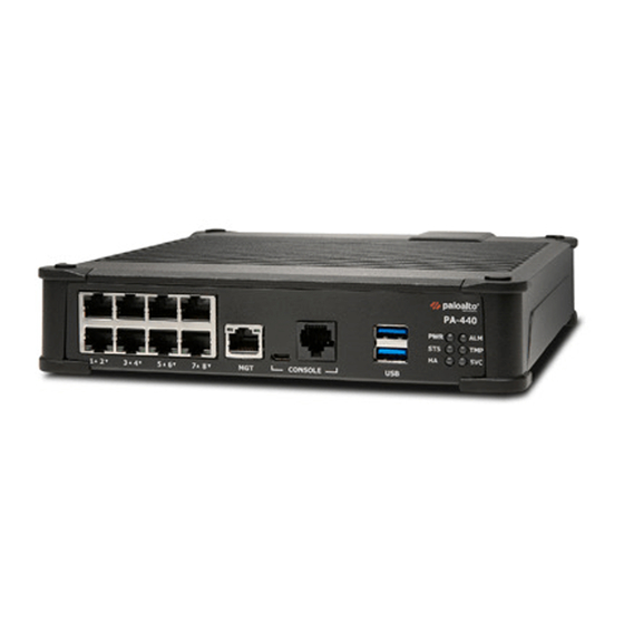
PA-400 Series next-generation firewall. (PA-440, PA-450, or PA-460)
1
Power adapter.
1
Power Cord, AC, North America, 10A/125V, 75C, 1.8M, St., SVT, NEMA-5-15P (YP-12) to IEC-C13 (YC-12).
1
Standard Type-A USB to micro USB console cable.
1
Shielded RJ-45 CAT6 Ethernet cable for management (MGT) port access.
6
Wood screws (.75") to mount the firewall and power adapter bracket to wood studs or plywood.
6
Drywall anchors and screws (1.25") to mount the firewall and power adapter bracket to a drywall or similar material that cannot
securely accommodate wood screws.
1
Power adapter wall-mount kit (includes one (1) each of the following: a power adapter bracket, a Velcro strap, and a plastic
cable tie).
1
Sheet, Limited Warranty.
1
China RoHS declaration.
2
Install the Firewall
There are three ways to install the PA-400 Series firewall:
◼
On a flat surface
◼
On a wall
◼
In a 19" equipment rack
Install the Firewall on a Flat Surface
The PA-400 Series firewalls ship with rubber "feet" attached to each corner of the device. The PA-440, PA-450, and PA-460 can
be set both horizontally and vertically upon a flat surface. See Figure 1 and Figure 2.
docs.paloaltonetworks.com
https://docs.paloaltonetworks.com/hardware
Figure 1
Figure 2
Install the Firewall on a Wall
1
Temporarily secure the Wall Mount Template (on this sheet) to the wall where you intend to mount the
firewall and use it to mark the location for each of the three wall-mount screws (Figure 3). Use a pointed
object to punch through the paper and visibly mark the wall; then remove the template and verify
measurements.
Ensure there are no building services (water, gas, or wiring) behind the wall where you intend to install
the firewall.
2
Use a Phillips-head screwdriver to install the appropriate screws into each of the three marked
locations:
◼
Drywall—First press a drywall anchor slightly into the center of a template mark. Then use your
screwdriver to apply pressure while turning the anchor clockwise until the surface of the anchor is
flush with the wall. After the drywall anchor is secure, install a 1.25" anchor screw into the anchor
until the bottom of the screw head protrudes ¼" from the wall. Repeat this step for the other two
screw locations. If any screw location is located over wood, use a .75" wood screw instead of a
drywall anchor and screw.
◼
Plywood wall—Use your screwdriver to insert a .75" wood screw into the center of each template
mark that is located over wood until the bottom of the screw heads protrude ¼" from the wall.
3
Align the three holes on the bottom of the firewall with the three screws on the wall and hang the
firewall on the screws (Figure 3).
4
Install the power adapter in the power adapter wall-mount bracket using the Velcro strap and cable tie
(Figure 4). Make sure to align the cable tie with the notches in the bracket to prevent the power cord
from falling out.
5
Mount the power adapter wall-mount bracket next to the firewall (Figure 5) using wood or drywall
screws as appropriate. You can install an optional second power adapter next to the first power adapter
for power redundancy.
Page 1 of 2
Quick Start Guide
7.5 cm
Wall Mount Template
Figure 3
Advertisement

Related Manuals for PaloAlto Networks PA-400 Series


Summary of Contents for PaloAlto Networks PA-400 Series
- Page 1 Ensure there are no building services (water, gas, or wiring) behind the wall where you intend to install the firewall. The PA-400 Series firewalls ship with rubber “feet” attached to each corner of the device. The PA-440, PA-450, and PA-460 can Use a Phillips-head screwdriver to install the appropriate screws into each of the three marked be set both horizontally and vertically upon a flat surface.
- Page 2 Contact your Panorama administrator if you require further assistance. Figure 6 Where To Go Next To learn more about the firewall, refer to the PA-400 Series Next-Gen Firewall Hardware Reference Guide: https://docs.paloaltonetworks.com/hardware. To learn how to configure Palo Alto Networks firewalls, go to the Technical Documentation portal: https://docs.paloaltonetworks.com.
Need help?
Do you have a question about the PA-400 Series and is the answer not in the manual?
Questions and answers