Table of Contents
Advertisement
Quick Links
Advertisement
Table of Contents

Related Manuals for ANEMOI AIRPRO M


Summary of Contents for ANEMOI AIRPRO M
- Page 1 AIRPRO [M] Installation Manual Issued January 2020 ANIM08AI Rev. A...
- Page 2 AIRPRO [M] UPDATES DATE UPDATE DESCRIPTION 26 / 02 / 2020 First Edition Technical documents are regularly updated. Anemoi reserves the right to modify the contents of this manual, in full or in part, without warning.
-
Page 3: Table Of Contents
AIRPRO [M] TABLE OF CONTENTS SAFETY .................................. 4 INTRODUCTION ............................5 TECHNICAL CHARACTERISTICS ....................... 6 DIMENSIONS ..............................7 DELIVERY ..............................8 Package Dimensions & Weights ......................8 Packing List ............................8 Fan diagram ............................10 MECHANICAL INSTALLATION ........................11 Clearances ............................12 Installation Tools .......................... -
Page 4: Safety
AIRPRO [M] SAFETY Thank you for purchasing our products! Please read this manual carefully before use, use the product accordingly and keep the manual in safe place. Installation work and electrical wiring must be done by qualified person(s) in accordance with all applicable codes and standards. -
Page 5: Introduction
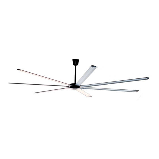
1 INTRODUCTION The AIRPRO M series is a light fan of up to 34kg that can be installed in up to seven meters height ceilings. This fan has been designed to be very easy to install. Depending on the control mode, the RF drive is integrated in the brushless motor and the Modbus drive is located in the ceiling mount. -
Page 6: Technical Characteristics
AIRPRO [M] 2 TECHNICAL CHARACTERISTICS AIRPRO 250 M AIRPRO 300 M AIRPRO 350 M AIRPRO 400 M GENERAL CHARACTERISTICS Diameter 2.5 m 3.0 m 3.6 m 4.0 m Blades number 7 aluminium blades Standard colour Black matte colour and aluminium blades MOTOR CHARACTERISTICS Motor power 350W... -
Page 7: Dimensions
3 DIMENSIONS The Anemoi Airpro [M] has four different diameters. The height of the fan can also be varied by changing the length of the extension rod. The next figure shows the fan dimensions with an extension drop of 643 mm:... -
Page 8: Delivery
AIRPRO [M] 4 DELIVERY The Anemoi Airpro [M] fan is delivered in two wood boxes, one including the motor parts and the other the blades. Handle the fan boxes carefully and with proper lifting equipment to avoid any damage. CAUTION! Use proper lifting equipment to handle the motor and blade boxes. - Page 9 AIRPRO [M] Component name Mounting Bracket shim 2 pcs I beam shim 4 pcs I beam clamp 2 pcs Extension tube clamp 2 pcs Guy wire bracket 2 pcs Turn buckle 4 pcs Beam clamp set 4 pcs Ferrite Bead Clamp 1 pc Earth Wire 1 pc...
-
Page 10: Fan Diagram
AIRPRO [M] 4.3 Fan diagram H – Extension tube A - Wire rope clamp B - Safety cable I – Extension tube shield C - I beam clamp J – Extension tube clamp D - I beam shim K – Guy wire bracket E - Mounting base L –... -
Page 11: Mechanical Installation
The Anemoi Airpro [M] fan is designed for ceiling installation. Ensure that the ceiling area chosen can hold the weight of the fan and that there are no obstacles in its operating range. The maximum weight of the fan is about 34 kg and the maximum torque is about 24Nm. -
Page 12: Clearances
5.1 Clearances In order to ensure the maximum coverage of the Anemoi Airpro [M], all obstacles that may be encountered within the radius of the fan and between the horizontal height of the fan's static position and the ceiling should be considered before installation, ensuring that the fan has an appropriate clearance in all directions when running. -
Page 13: Installation Tools
AIRPRO [M] 5.2 Installation Tools To install the fan, ensure having the following required tools: Name Quantity Standard wrench set Standard socket set with ratchet Standard Allen wrench set Phillips screwdriver Hydraulic cutter Torque wrench Flat head screwdriver Multimeter Pair of #10 to #14 AWG strippers 5.3 I-Beam Conditions In case of I-Beam installation, make sure the minimums requirements are met: Please consult with structural engineer to make sure your building is approved for fan installation. -
Page 14: Pre-Installation Checklist
AIRPRO [M] 5.4 Pre-installation Checklist Before installation, make sure the following requirements are met: Check Description The fan can only be mounted to the I-beam or a concrete beam. DO NOT mount the fan directly to a single stringer, truss shelf or light steel shelf. For installation methods not included in this manual, please consult a structural engineer. -
Page 15: Ceiling Mount Bracket
5.5 Ceiling Mount Bracket The Anemoi Airpro [M] comes with mounting brackets (Mounting Base) to anchor the fan to the ceiling. As standard, all tooling is provided so that the fan can be mounted in I beams or concrete beams. The fan is prepared to be installed in inclined roofs. -
Page 16: Extension Rod Assembly
AIRPRO [M] 5.6 Extension Rod Assembly The extension rod is assembled to the ceiling fixation by the cardan joint. The cardan joint allows also the fan to make free oscillation and to find its own level position specially for inclined roofs. The extension rod is assembled to the ceiling fixation by the Screws provided, it must be tightened to avoid balancing the extension. -
Page 17: Motor Assembly
AIRPRO [M] 5.7 Motor Assembly The motor is assembled to the extension rod by the three M8*55 bolt set provided. It is very important that the extension rod stays vertical to avoid abnormal operation. 6. Insert the motor tube in the extension tube clamp, then take out the earth wire and guy wire bracket as picture shown. -
Page 18: Safety Cable Installation
AIRPRO [M] 5.8 Safety Cable Installation The engine box contains a safety cable that must be installed to prevent the engine from failing after assembly. To do so, please use four Wire Rope Clamp and the Safety Cable that is provided in the motor box. If the fan is mounted on a steel or concrete beam, wrap the beam with the safety cable in a closed loop as shown below: 7-1. -
Page 19: Wiring Location
AIRPRO [M] 5.9 Wiring Location 8-1. Through Ground, Line and Neutral wires into Ferrite Bead Clamp, and wrap a circle. 8-2. Connecting the Ground, Line and Neutral wires with motor and indoor wiring. Please refer to “Wiring Diagram” at section 6 Electrical installation. L: Line wire N: Neutral wire E: Ground wire... -
Page 20: Extension Tube Shield Installation
AIRPRO [M] 5.10 Extension Tube Shield Installation The extension tube shield is provided in order to protect the safety cable and wiring. To do so, please use four bolts of the Extension tube shield bolt kit that is provided in the motor box, as shown below: 9. -
Page 21: Guy Wires Fixation (Optional)
AIRPRO [M] 5.11 Guy Wires Fixation (optional) If oscillations are detected, winds must be installed as part of the assembly process. The use of winds is recommended for extensions greater than the standard extension. To do so, there is an auxiliary hardware with Turn Buckle, Wire Rope Clamp and Beam Clamp set. - Page 22 AIRPRO [M] 13. Once the two sides of turnbuckle with wire rope clamp and the safety cable are properly tighten, refer to the fasten instruction as picture shown. Adjust the turn buckle to make sure the ceiling fan reach the balance. Repeat this step 4 times to complete Wires Fixation.
-
Page 23: Blades Assembly
AIRPRO [M] 5.12 Blades Assembly To assemble the blades, it is necessary to screw the plastic end caps, and introduce and fix them to the motor guides. Use the M6 bolts to fix the plastic end caps before lifting the blade to the motor. 14. -
Page 24: Electrical Installation
6 ELECTRICAL INSTALLATION The Anemoi Airpro [M] fan can be purchased with remote control or with Modbus control. In the following sections, the particularities of each of the two models are established. Depending on the options, the drive is located as... -
Page 25: Remote Control Fan Installation
AIRPRO [M] The Anemoi Airpro [M] engine must be connected to the power supply with an electrical voltage of 200-240V (I, 50/60Hz). Please see the voltage and consumption for this HVLS fan on the technical characteristics to guarantee a properly installation. -
Page 26: Remote Control
AIRPRO [M] 6.1.2 Remote Control The Anemoi AIRPRO [M] fan is operated through a remote control. The remote control comes paired from factory with the fan. Remote Control Battery installation. 1. Remove the battery cover and install two AAA batteries. -
Page 27: Modbus Installation
The Anemoi Airpro [M] fan with Modbus control must be connected to the power supply with an electrical voltage of 200-240V (I, 50/60Hz). The Anemoi Airpro [M] fan needs an external control to work. The external control is connected directly to the fan control board using shielded cable type Modbus cable RS485 2x2x0.50 mm² POSCY. - Page 28 AIRPRO [M] Electrical and data connections are shown below: A circuit breaker must be installed for each fan, it is recommended an 20mA Circuit Breaker. In other to avoid motor damages. WARNING! Never mix electrical and control wiring. Doing so may lead to interference. A 20mA circuit breaker must be installed for each fan.
-
Page 29: Multi Fans Installation
AIRPRO [M] 6.2.2 Multi Fans Installation In installations with multiple fans, it is possible to control the fans using a single controller. In this case, the controller is connected to the different by using control connections. The connection must be made in series. The next figure shows the correct connections: WARNING! Never mix electrical and control wiring. -
Page 30: Recommendations
AIRPRO [M] 6.2.3 Recommendations To ensure correct installation and functioning of the Modbus control fan, please keep in mind following recommendations: 1- Please strip the wire 5cm as a maximum as shown below: 2- Communication cables cannot be wound. If it were done, they could act as an antenna. Communication cables that are not used have to be cut and left inside the shielded tube as shown below. -
Page 31: Maintenance
AIRPRO [M] 7 MAINTENANCE WARNING! Do NOT repair or clean the fan while it is in operation or connected to the power supply. Doing so may result in serious or fatal electrical shock. Please maintain the fan as follows: Every three months: •... -
Page 32: Troubleshooting
AIRPRO [M] 8 TROUBLESHOOTING WARNING! Do NOT make any inspection of the fan while it is in operation or connected to the power supply. Doing so may result in serious or fatal electrical shock. In case of failure, refer to the following table for quick solutions: Observation Probable cause Inspection method... - Page 33 www.anemoifans.com...
Need help?
Do you have a question about the AIRPRO M and is the answer not in the manual?
Questions and answers