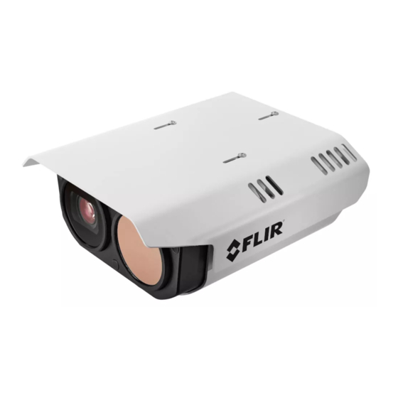
Table of Contents
Advertisement
Quick Links
1 Check Contents
The camera kit includes a bag containing:
·
a T10 Torx wrench
·
two 10-pin connectors for I/O terminal blocks
·
one three-pin connector for 12 VDC terminal block
·
three two-pin connectors for 24 VAC output / input terminal blocks
In addition, watertight cable glands and seal plugs are attached to the camera's
rear cable ingress holes.
If any of these items are missing or damaged, contact your dealer or
FLIR
Support.
2 Select a Location
Triton FH-Series cameras are intended to be mounted on a medium-duty fixed
pedestal mount or wall mount commonly used in the CCTV industry, at an
installation height of at least 4 m (13 ft). The mount must support up to 30 lbs (15
kg). For the full list of mounting and other accessories available for the camera
from Teledyne FLIR, see the FLIR Security - Accessory Guide.
If you are powering the camera with PoE 70W class 8 or 24V AC / DC, verify that
the operating temperature is -40°C to 70°C (-40°F to 158°F) with cold start at -40°
C (-40°F), 0-95% relative humidity. Other power sources limit low-temperature
operation. For more information, see the camera's installation and user guide.
For further advice on positioning and orienting the camera, see the camera's
installation and user guide.
Supplying Power to the Camera
The camera can be powered by 12 VDC (±10%); 24 VDC (±10%); 24 VAC
(±10%); or PoE IEEE 802.3bt 50W class 6 or 70W class 8. Teledyne FLIR
recommends using PoE class 8 or 24 VAC / VDC.
Nominal power consumption is 15W; 48W on 12 VDC with heaters enabled; and
70W on all other input voltages with heaters enabled.
427-0102-00-28 Triton FH-Series QIG Rev 110
This document does not contain any export-controlled information.
Triton™ FH-Series
Quick Install Guide
Teledyne
November 2021
Advertisement
Table of Contents

Summary of Contents for Teledyne FLIR Triton FH-Series
- Page 1 Supplying Power to the Camera The camera can be powered by 12 VDC (±10%); 24 VDC (±10%); 24 VAC (±10%); or PoE IEEE 802.3bt 50W class 6 or 70W class 8. Teledyne FLIR recommends using PoE class 8 or 24 VAC / VDC.
-
Page 2: Connect The Camera
3 Connect the Camera To install the camera, Teledyne FLIR recommends connecting the camera on a bench or in a lab and configuring it for networking before mounting and aiming it. However, circumstances can dictate adjusting the sequence of the steps. For example, you can mount the camera before configuring it for networking, or connect the camera before mounting it. - Page 3 You do not need to remove the sunshield to open the cover. Nonetheless, if you want to remove the sunshield, loosen and remove the screws that attach it to the camera body. Then, carefully remove the sunshield. b. Open the camera cover to expose the inside of the camera body and the following connections.
- Page 4 Connection Description Connect wires from alarm or audio I/O devices, or from IR LED 10-pin terminal illuminators, to the appropriate pins on a ten-pin connector included block x 2 in the camera kit. Then, plug the connectors into the terminal blocks. To use the camera's external IR illumination feature to turn illuminators on and off, connect them to ALARM OUT 2.
- Page 5 Teledyne FLIR's Horizon or Meridian VMS and the VMS is configured as a DHCP server, the VMS automatically assigns the camera an IP address. If the camera is managed by Teledyne FLIR’s Latitude VMS or is on a network with static IP addressing, you can manually specify the camera’s IP address using the DNA tool or the camera's web page.
-
Page 6: Mount The Camera
5 Mount the Camera Teledyne FLIR offers accessories to mount the camera on a wall, on a large pole, on a small pole, in a corner, or on a pedestal. For more information about the accessories required for each mounting option, see the camera's installation and user guide. - Page 7 Carefully following these instructions makes sure water does not enter the camera and ensures its long-term reliability. Caution Teledyne FLIR is not responsible for damage to the camera due to not adhering to these instructions. Cables enter the camera body through liquid-tight 3/4"...
- Page 8 To ensure a watertight seal, fully tighten the gland nuts. Close and Secure the Cover Using the Torx wrench, alternately tighten the four screws that secure the cover to the camera; torque to 8+0.5 kgf-cm. To ensure the camera's IP66 and IP67 dust and water ingress ratings, properly and securely close the camera cover and Caution tighten the screws.
- Page 9 h. Click Display Target. A box simulating a 1.8m (5" 11') person appears in the live video. Make sure the height of the box corresponds to the size of the person standing in the camera's field of view. If it does not, on the Georeference page, verify the camera's installation height, tilt angle, and roll angle.
-
Page 10: Camera Dimensions
10 Attach the Camera to a Supported VMS After you have mounted the camera and discovered or defined its IP address, attach the camera to a supported VMS using its discovery/attach procedure. 11 Camera Dimensions The Triton FH-Series camera’s dimensions are: 12 Register the Product Register the product at https://customer.flir.com.


Need help?
Do you have a question about the FLIR Triton FH-Series and is the answer not in the manual?
Questions and answers