
Related Manuals for Phoenix Contact SHDSL-PROFIBUS


Summary of Contents for Phoenix Contact SHDSL-PROFIBUS
- Page 1 INTERFACE User manual UM EN PSI-MODEM-SHDSL/PB Order No.: — SHDSL-PROFIBUS permanent line modem, for line and star structures on plant's own copper cables...
- Page 3 INTERFACE User manual SHDSL-PROFIBUS permanent line modem, for line and star structures on plant's own copper cables 2011-04-27 Designation: UM EN PSI-MODEM-SHDSL/PB Version: Order No.: — This user manual is valid for: Designation Revision Order No. PSI-MODEM-SHDSL/PB 2313656 104274_en_00 PHOENIX CONTACT...
- Page 4 Phoenix Contact accepts no liability for erroneous handling or damage to products from Phoenix Contact or third-party products resulting from disregard of information contained in this user manual.
- Page 5 The receipt of technical documentation (in particular data sheets, installation instructions, manuals, etc.) does not constitute any further duty on the part of Phoenix Contact to furnish information on alterations to products and/or technical documentation. Any other agreement shall only apply if expressly confirmed in writing by Phoenix Contact.
- Page 6 Phoenix Contact. Violators are liable for damages. Phoenix Contact reserves all rights in the case of patent award or listing of a registered design, in as far as this concerns software of Phoenix Contact that meets the criteria of technicity or has technical relevance.
-
Page 7: Table Of Contents
Connection mode ................3-4 Configuration ......................3-5 3.4.1 Point-to-point and linear structure wizard ..........3-6 3.4.2 Setting default settings ..............3-12 Diagnostics.......................3-13 3.5.1 Device status ..................3-13 3.5.2 Event log ................... 3-15 3.5.3 Value log ................... 3-16 Transfer ......................3-17 Firmware update....................3-18 104274_en_00 PHOENIX CONTACT... - Page 8 Setting the programming adapter ............5-4 Manually setting bus parameters................ 5-7 5.2.1 Determining set bus parameters ............5-7 5.2.2 Selecting and setting the programming adapter ........5-8 Eliminating errors ........................6-1 Frequent error causes ..................6-1 Diagnostic IDs ....................6-1 PHOENIX CONTACT 104274_en_00...
-
Page 9: Description Of The Shdsl Permanent Line Modem
Suitable for the plant's own cables, not for public telephone networks – Point-to-point connection – Linear structure, up to 30 SHDSL devices – Mixed operation with PROFIBUS infrastructure components from Phoenix Contact SHDSL – Symmetrical data transmission – Up to 15.3 Mbps (2-wire) –... -
Page 10: Ordering Data
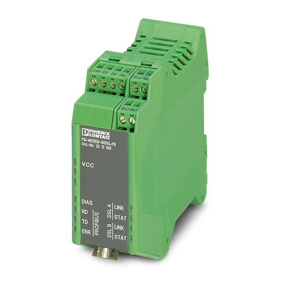
VCC (green LED) – Steady light: Operation – Flashes at 1 Hz: supply via USB (for configuration) Switching outputs 2 x U nom/150 mA (the digital outputs cannot be used to supply power via the TBUS), short-circuit-proof PHOENIX CONTACT 104274_en_00... - Page 11 MTBF according to Telcordia standard Ambient temperature of 25°C 1004 years Ambient temperature of 40°C 199 years Test voltage 1.5 kV AC, 50 Hz Vibration resistance According to IEC 60068-2-6: 5g, 150 Hz Electromagnetic compatibility Conformance with EMC Directive 2004/108/EC 104274_en_00 PHOENIX CONTACT...
-
Page 12: Housing Dimensions
For these devices, there are further requirements according to EN 50121-4 Table 1, Note 1. Section 1, Paragraph 3 of EN 50121-4 applies. Phoenix Contact QUINT power supply units are to be used directly on the device. Conformity assessment in acc. with 94/9/EC... -
Page 13: Topologies
Greater data rates or ranges are possible when high quality cables with larger diameters are used. The industrial SHDSL permanent line modems from Phoenix Contact enable data rates in 2-wire operation from 32 kbps to 15.3 Mbps. The SHDSL-PROFIBUS permanent line modems are suitable for the plant's own cables, not for the public telephone networks. -
Page 14: Point-To-Point Connection
PROFIBUS data rate must not be automatically excluded from the maximum possible SHDSL data rate. You can have the possible data rates calculated using the PSI-CONF configuration software. The PROFIBUS data rate for a point-to-point connection is up to 1.5 Mbps PHOENIX CONTACT 104274_en_00... -
Page 15: Linear Structure
PROFIBUS data rate must not be automatically excluded from the maximum possible SHDSL data rate. You can have the possible data rates calculated using the PSI-CONF configuration software. The PROFIBUS data rate for a linear structure is up to 500 kbps 104274_en_00 PHOENIX CONTACT... -
Page 16: Star Structure With Shdsl Devices
You can find a description of how to set the slot time using the SIMATIC Manager software - Step 7 at "Setting slot time in the PROFIBUS master" on page 4-5. Here, we describe the procedure for the SIMATIC Manager, Version 5.x. PHOENIX CONTACT 104274_en_00... - Page 17 PROFIBUS devices per segment is lowered (max. 31) and the segments are not electrically isolated. T-BUS PROFIBUS max. 31 max. 31 max. 31 max. 29 (31-2) PROFIBUS Not recommended! Recommended! Figure 1-7 Examples for head stations 104274_en_00 PHOENIX CONTACT...
-
Page 18: Mixed Structures (Special Cases)
PSI-MODEM-SHDSL/PB 1.5.4 Mixed structures (special cases) Mixed operation with PROFIBUS infrastructure components from Phoenix Contact SHDSL 2-wire max. 31 path redundancy SHDSL SHDSL max. 31 max. 31 max. 31 max. 31 max. 31 Figure 1-8 Mixed operation with PROFIBUS infrastructure components By means of the DIN rail connector, you can easily combine SHDSL modems with other Phoenix Contact PROFIBUS infrastructure components. -
Page 19: Installing Hardware
20 seconds after booting. The devices are configured using the PSI-CONF configuration software. The configuration software calculates the slot time depending on the SHDSL data rate and the topology. You must set this slot time in the PROFIBUS master. 104274_en_00 PHOENIX CONTACT... -
Page 20: Mounting The Module On A Din Rail
Use a suitable screwdriver to release the locking mechanism on the snap-on foot of the device (see Figure 2-1 B). • Hold the device onto the housing cover and carefully tilt it upward. • Carefully lift the device off the DIN rail. PHOENIX CONTACT 104274_en_00... -
Page 21: Mounting With Din Rail Connectors (Connection Station)
Carefully push the housing cover in the direction of the mounting surface so that the device bus connector is fixed securely on the DIN rail connector. • Once the snap-on foot has been snapped onto the DIN rail, check that it is fixed securely. 104274_en_00 PHOENIX CONTACT... -
Page 22: Description Of The Connections And Leds
Link device found Flashing (2 Hz) Initializing connection 15 STAT (yellow) DSL ports No connection established OFF (pulsating) (flashing every 3 s) connection quality sufficient ON (pulsating) (goes out every 3 s) connection quality good Connection quality very good PHOENIX CONTACT 104274_en_00... -
Page 23: Establishing Connections
WARNING: SELV operation The PSI-MODEM-SHDSL/PB was designed for SELV operation according to IEC 60950/EN 60950/VDE 0805 only. WARNING: The modem may only be connected to devices which satisfy the requirements of EN 60950 (safety of information technology equipment). 104274_en_00 PHOENIX CONTACT... -
Page 24: Dsl Connection
For a 2-wire connection, connect DSL port A (a and b) to DSL port B (a and b) of the next modem. Connect a and b as desired. DSL port B of the first device and DSL port A of the last device are not used. PHOENIX CONTACT 104274_en_00... - Page 25 Short flashing of the green "LINK" LEDs indicates that the DSL port is not disabled. Both "STAT" LEDs provide information on the quality of the connection. The longer the LED lights up, the better the quality of connection (see Page 2-4). 104274_en_00 PHOENIX CONTACT...
-
Page 26: Connecting Switching Outputs
DSL B DIO = "24 V" good to very good connection DIO = "open" no or only moderately good connection Connecting • Connect the cable to the corresponding screw terminal block. PHOENIX CONTACT 104274_en_00... -
Page 27: Connecting The Profibus Interface (Rs-485)
Please note that the "ERR" LED can also refer to an SHDSL connection. The RD and TD LEDs can also flash when there is no DSL connection, such as when there is communication between the DIN rail connector and the D-SUB connector. 104274_en_00 PHOENIX CONTACT... -
Page 28: Connecting To A Usb Interface
The USB interface cannot be used for data transmission. DSL operation is not possible via the USB supply. • Connect the Mini USB connector (type B) to the modem and the USB connection to your computer. 2-10 PHOENIX CONTACT 104274_en_00... -
Page 29: Connecting The Supply Voltage
• Connect the 24 V supply voltage to the "24 V" and "0 V" connection points. As soon as the "VCC" LED lights up, the modem is ready. 24V 0V Figure 2-8 Connecting the supply voltage 2-11 104274_en_00 PHOENIX CONTACT... - Page 30 +24 V +24 V ³ 40 mm -20 °C ... +60 °C +24 V -20 °C ... +50 °C +24 V -20 °C ... +45 °C £ 8 PSI-MODEM-SHDSL/PB Figure 2-9 Temperature range for PROFIBUS devices 2-12 PHOENIX CONTACT 104274_en_00...
-
Page 31: Use In Potentially Explosive Areas
WARNING: Explosion hazard Only devices which are designed for operation in zone 2 potentially explosive areas and are suitable for the conditions at the installation location may be connected to the signal circuits in zone 2. 2-13 104274_en_00 PHOENIX CONTACT... - Page 32 PSI-MODEM-SHDSL/PB 2-14 PHOENIX CONTACT 104274_en_00...
-
Page 33: Configurable Via Psi-Conf
DSL connection DSL B DIO = "24 V" good to very good DSL connection DIO = "open" no or only moderately good DSL connection A combination of different SHDSL modems (e.g., from PSI-MODEM-SHDSL/PB and PSI-MODEM-SHDSL/ETH) is not possible. 104274_en_00 PHOENIX CONTACT... -
Page 34: Installing Psi-Conf
To start the software, Microsoft NET Framework 2.0 must be installed on your computer. If not already installed, it will be installed automatically. You also require a USB driver, which is installed automatically during software installation. For further instructions, please refer to the help file for the installation program. PHOENIX CONTACT 104274_en_00... -
Page 35: Getting Started
PSI-CONF is started in English or German depending on the operating system. You can select the desired language. • To do this, click on "Language"/"Sprache" in the menu at the top left and select "English - Englisch" or "German - Deutsch". 104274_en_00 PHOENIX CONTACT... -
Page 36: Selecting The Device
A new window appears when you click on "Configuration file". Here you can choose between "New project" or "Open project". The configuration is created and saved on the computer in offline mode. It is subsequently transmitted to the modem. PHOENIX CONTACT 104274_en_00... -
Page 37: Configuration
DIN rail connector (see "Star structure with SHDSL devices" on page 1-8). Linear structure wizard Configuring a linear structure for a 2-wire connection. A network can be configured via several steps for up to 30 SHDSL devices. 104274_en_00 PHOENIX CONTACT... -
Page 38: Point-To-Point And Linear Structure Wizard
Each device already has a name (device 1, device 2...). You can select a device by names clicking it or via the "Last device"/"Next device" menu and assigning a name, e.g. "Modem A" or "Pumping station". The name can contain 255 characters including special characters. PHOENIX CONTACT 104274_en_00... - Page 39 When the DSL data rate is set to "Manual", the slot time and the maximum PROFIBUS data rate are not calculated with the "Expected data rate" but just with the data rate provided. Further information about data rates can be found at "Optimizing and setting PROFIBUS" on page 4-1. 104274_en_00 PHOENIX CONTACT...
- Page 40 Holding down the mouse button, move the devices available in the device list to the gray area under the SHDSL modem. • To remove a device, delete it from the device list in the same way. • Select the transmission speed in kbps. Repeat the steps for all SHDSL modems. PHOENIX CONTACT 104274_en_00...
- Page 41 You can find a description of how to set the slot time using the SIMATIC Manager software - Step 7 at "Setting slot time in the PROFIBUS master" on page 4-5. Here, we describe the procedure for the SIMATIC Manager, Version 5.x. 104274_en_00 PHOENIX CONTACT...
- Page 42 You can set the configuration for each individual modem. If the configuration is the same for each modem, click on the "Accept for all" button. Step 6: Summary A summary of the settings is provided here. You can print out the settings via the "Print" button. 3-10 PHOENIX CONTACT 104274_en_00...
- Page 43 You can find a description of how to set the slot time using the SIMATIC Manager software - Step 7 at "Setting slot time in the PROFIBUS master" on page 4-5. Here, we describe the procedure for the SIMATIC Manager, Version 5.x. 3-11 104274_en_00 PHOENIX CONTACT...
-
Page 44: Setting Default Settings
DSL A, DO = "open", in the case of "no or only moderate connection" DSL B, DIO = "24 V", in the case of "good to very good connection" DSL B, DIO = "open", in the case of "no or only moderate connection" 3-12 PHOENIX CONTACT 104274_en_00... -
Page 45: Diagnostics
Indicates the status of the diagnostics output (DO). If the event linked to the port occurred, the status is "set". The physical port status is specified in brackets, which can be either "open" or "24 V". 3-13 104274_en_00 PHOENIX CONTACT... - Page 46 DSL path. Link quality Quality of the DSL connection to Port A or B. Network load (RX/TX) Network load for outgoing (TX) and incoming (RX) data traffic. Error diagnostics Indicates how strongly SHDSL data traffic is disturbed. 3-14 PHOENIX CONTACT 104274_en_00...
-
Page 47: Event Log
"Diagnostic IDs" on page 6-1. Event description The description of the event. Port The port to which the event is assigned. Seconds since boot The time in seconds between the event and the time of the last boot procedure. 3-15 104274_en_00 PHOENIX CONTACT... -
Page 48: Value Log
Indicates the status of the connection. Link status PROFIBUS Shows the status of the PROFIBUS connection via the DSUB status device's D-SUB interface. PROFIBUS Shows the status of the PROFIBUS connection via the T-BUS TBUS status DIN rail connector. 3-16 PHOENIX CONTACT 104274_en_00... -
Page 49: Transfer
There are two options: You can open an existing file and save to the modem connected via USB. You can read the existing configuration and save it to a file. The file extension is ".dat". 3-17 104274_en_00 PHOENIX CONTACT... -
Page 50: Firmware Update
Release date The date the firmware was released. Update firmware Open firmware Find and open firmware file (.bin) on data carriers. Firmware file Name of the open firmware file Firmware version Firmware version of the update 3-18 PHOENIX CONTACT 104274_en_00... - Page 51 Configurable via PSI-CONF Update firmware Release date The date the firmware to be installed was released. Start update The selected firmware file is transferred to the device con- nected via USB. 3-19 104274_en_00 PHOENIX CONTACT...
- Page 52 PSI-MODEM-SHDSL/PB 3-20 PHOENIX CONTACT 104274_en_00...
-
Page 53: Optimizing And Setting Profibus
Using the diagnostic function, display the actual SHDSL data rate on the path (see "Device status" on page 3-13). • Open the existing project and set the DSL data rate to "manual" (see "Step 3: DSL line configuration" on page 3-7). 104274_en_00 PHOENIX CONTACT... - Page 54 The new values will be used to calculate the PROFIBUS data rate and the slot time. If, despite this optimization, the desired PROFIBUS data rate is not displayed in the program, you must operate your system with a lower data rate. PHOENIX CONTACT 104274_en_00...
-
Page 55: Increasing Immunity To Interference
The SHDSL data rate must always be smaller than the MaximumImmunitytoInterference configuration software's calculated SHDSL data rate. If the SHDSL data rate is greater than the configuration software MaximumImmunitytoInterference data rate, you must reduce the PROFIBUS data rate. 104274_en_00 PHOENIX CONTACT... -
Page 56: Setting Profibus
With the PROFIBUS master, you must set the slot time using the TSlot_Init parameter. We show you how this parameter is set in the PROFIBUS master with an example from the SIMATIC Manager (Version 5.x), see "Setting slot time in the PROFIBUS master" on page 4-5. PHOENIX CONTACT 104274_en_00... -
Page 57: Setting Slot Time In The Profibus Master
Simatic Manager The following window appears. Figure 4-2 NetPro Step 2 • In the "NetPro" window, right-click the PROFIBUS line to which you would like to connect your programming device. • In the context menu, open "Object Properties". 104274_en_00 PHOENIX CONTACT... - Page 58 The most recently valid bus parameters are shown in this window. • Enter the slot time in the "Tslot_Init" field. The configuration software calculates the slot time (see "Step 7: Transfer" on page 3-11). You can read it there. PHOENIX CONTACT 104274_en_00...
- Page 59 • Click on the "Re-calculate" button. To send the settings to the master, proceed as follows: • Go back to the "NetPro" view. • Select "Save and Compile" and then transfer all settings to your PROFIBUS master. 104274_en_00 PHOENIX CONTACT...
- Page 60 PSI-MODEM-SHDSL/PB PHOENIX CONTACT 104274_en_00...
-
Page 61: Using Programming Devices
PROFIBUS data rates under 187.5 kbps. The reason for this is a timeout time within the programming device that is too short. In this case, it is not on the SHDSL route. For PROFIBUS data rates under 187.5 kbps, we recommend using a V.24 (RS-232) programming adapter. 104274_en_00 PHOENIX CONTACT... -
Page 62: Setting Automatic Detection Of Bus Parameters
SIMATIC Manager, Options menu The following window appears. Figure5-2 NetPro Step 2 • In the "NetPro" window, right-click the PROFIBUS line to which you would like to connect your programming device. • In the context menu, open "Object Properties". PHOENIX CONTACT 104274_en_00... - Page 63 Figure5-4 NetPro, Object Properties, Bus parameters Step 4 • Make sure that the "Turn on cyclic distribution of the bus" field is checked. If the checkmark was already placed, you can proceed with setting the programming adapter. 104274_en_00 PHOENIX CONTACT...
-
Page 64: Setting The Programming Adapter
In the menu, choose "Options, Set PG/PC Interface". Step 3 The following window appears. Figure5-6 NetPro, Options, Set PG/PC Interface • Choose the "PC Adapter (Auto)" programming adapter from the list. • Then click the "Properties" button. PHOENIX CONTACT 104274_en_00... - Page 65 In the "Properties - (Adapter name)(Auto)" dialog box, click "Start Network Connection" (see "Step 4" on page 5-3). The PROFIBUS data rate used should be detected relatively quickly. A maximum wait time needed to determine the remaining PROFIBUS parameters will also be displayed: 104274_en_00 PHOENIX CONTACT...
- Page 66 Close all dialog boxes by selecting "Close" and "OK". After closing the last dialog box, a warning appears. Figure5-10 Warning • Acknowledge this warning by pressing "OK". You have now successfully configured your programming device to automatically detect bus parameters. You can now use your programming device. PHOENIX CONTACT 104274_en_00...
-
Page 67: Manually Setting Bus Parameters
Step 4 A dialog box appears that displays the parameters set for the bus system. You must have these values to hand later when configuring the programming adapter. • Note the values and close all open windows again. 104274_en_00 PHOENIX CONTACT... -
Page 68: Selecting And Setting The Programming Adapter
Open "Options, Configure Network" in the menu. Step 2 • In the menu, choose "Options, Set PG/PC Interface". Figure5-12 NetPro, Options, Set PG/PC Interface • Select the "PC Adapter (PROFIBUS)" programming adapter from the list. • Then click the "Properties" button. PHOENIX CONTACT 104274_en_00... - Page 69 Set how the programming device is connected to the PC (e.g., by USB or COM port. For COM port, the COM port to which the programming device is connected must be selected). Step 5 • In the dialog box, select the "User-Defined" profile and click on the "Bus Parameters" button. 104274_en_00 PHOENIX CONTACT...
- Page 70 Close all dialog boxes by selecting "Close" and "OK". After closing the last dialog box, a warning appears. Figure5-15 Warning • Acknowledge this warning by pressing "OK". You have now successfully configured your programming device. You can now use your programming device. 5-10 PHOENIX CONTACT 104274_en_00...
-
Page 71: Eliminating Errors
By an incorrect configuration of – Both devices must have the factory the link partner configuration By a data rate that was set too Reduce the data rate. high Reserved – – 104274_en_00 PHOENIX CONTACT... - Page 72 Defective PROFIBUS device Check whether errors originate from a driver (device emits signal level particular PROFIBUS device. If this is the that is too low) case, the device driver may be defective. Replace corresponding device. PHOENIX CONTACT 104274_en_00...
- Page 73 SHDSL-PB data rate to that of the SHDSL-PB device. device Check installation for correct connection of PROFIBUS cable A swapped with A and B cable B Check installation for short circuit PROFIBUS cable short circuit 104274_en_00 PHOENIX CONTACT...
- Page 74 Good link quality The link quality was determined This is particularly interesting if the link quality "good" was previously "Very good". If necessary, reduce the data rate or check the installation if more interference occurs. PHOENIX CONTACT 104274_en_00...
- Page 75 The SHDSL link is broken Check the remote PROFIBUS device power supply. The remote PROFIBUS device power supply was interrupted Check the PROFIBUS cable connected to the remote devices. The PROFIBUS cable connected to the remote device was disconnected 104274_en_00 PHOENIX CONTACT...
- Page 76 USB port device is supplied via the USB port only. No data traffic may take place, since the SHDSL chip is reset to save energy. DIAG LED set An error event caused the DIAG LED to be set PHOENIX CONTACT 104274_en_00...
- Page 77 PROFIBUS port telegrams can no longer collide. No PROFIBUS data lost The SHDSL port connection may have to the specified SHDSL been broken or the adverse effects port and overload of the corresponding port were only temporary. 104274_en_00 PHOENIX CONTACT...
- Page 78 PSI-MODEM-SHDSL/PB PHOENIX CONTACT 104274_en_00...
Need help?
Do you have a question about the SHDSL-PROFIBUS and is the answer not in the manual?
Questions and answers