
Related Manuals for HP 8163A


Summary of Contents for HP 8163A
- Page 1 HP 8163A Lightwave Multimeter & HP 8164A Lightwave Measurement System User’s Guide...
- Page 2 Product maintenance agreements HP. Buyer shall prepay shipping tutes’s calibration facility, and to 71034 Böblingen and other customer assistance charges to HP and HP shall pay the calibration facilities of other Germany agreements are available for shipping charges to return the International Standards Organi- Hewlett-Packard products.
- Page 3 HP 8163A Lightwave Multimeter & HP 8164A Lightwave Measurement System User’s Guide...
- Page 4 (covers, panels, and so on). Line Power Requirements The HP 8163A Lightwave Multimeter can operate from the single- phase AC power source that supplies between 100 V and 240 V at a frequency in the range 50 to 60 Hz. The maximum power...
- Page 5 Safety Summary The HP 8164A Lightwave Measurement System can operate from any single-phase AC power source that supplies between 100 V and 240 V at a frequency in the range from 50 to 60 Hz. The maximum power consumption is 270 VA with all options installed.
- Page 6 • Cable clamp. Operating Environment WAR NI NG The HP 8163A Lightwave Multimeter & HP 8164A Lightwave Measurement System is not designed for outdoor use. To prevent potential fire or shock hazard, do not expose the instrument to rain or other excessive moisture.
- Page 7 Safety Summary Additional safety requirements Operation - Before applying power Comply with the installation section. Additionally, the following shall be observed: • Do not remove instrument covers when operating. • Before the instrument is switched on, all protective earth terminals, extension cords, auto-transformers and devices connected to it should be connected to a protective earth via a ground socket.
- Page 8 Safety Summary Safety Symbols The apparatus will be marked with this symbol when it is necessary for the user to refer to the instruction manual in order to protect the apparatus against damage. Caution, risk of electric shock. Frame or chassis terminal. Protective conductor terminal.
- Page 9 Safety Summary Initial Safety Information for Tunable Laser Source Modules HP 81680A HP 81682A HP 81640A HP 81689A Laser Type Fabry Fabry Fabry Fabry Perot-Laser Perot-Laser Perot-Laser Perot-Laser InGaAsP InGaAsP InGaAsP InGaAsP Laser Class According to 21 IIIb IIIb IIIb IIIb CFR 1040.10 (USA)
- Page 10 Safety Summary NOT E USA (All Tunable Laser Source Modules HP 81640A/80A/82A/89A) These laser safety warning labels are fixed on the outside of the HP 8164A Lightwave Measurement System before shipment.
- Page 11 Safety Summary Non-USA (All Tunable Laser Source Modules HP 81640A/80A/82A/89A) These laser safety warning labels are fixed on the outside of the HP 8164A Lightwave Measurement System before shipment. A sheet of laser safety warnings is included with the laser module. You...
- Page 12 Safety Summary WARNIN G Use of controls or adjustments or performance of procedures other than those specified for the laser source may result in hazardous radiation exposure. WARNIN G Refer Servicing only to qualified and authorized personnel. WARNIN G Do not enable the laser when there is no fiber attached to the optical output connector.
- Page 13 Safety Summary...
- Page 14 Safety Summary The Structure of this Manual This manual is divided into 3 categories: • Getting Started This section gives an introduction to the instrument. and aims to make the instrument familiar to you: Chapters 1 and 2. • How to Use Modules This is the information on how to control modules from the front panel: Chapters 3, 4, and 5.
- Page 15 Additional safety requirements ........... 7 Initial Safety Information for Tunable Laser Source Modules 9 1 Getting Started 1.1 The HP 8163A Lightwave Multimeter ....27 1.2 The HP 8164A Lightwave Measurement System .28 1.3 A Description of the User Interface .......30 Password ................
-
Page 16: Table Of Contents
2.1 Using the System Utilities ........51 How to Set the Backlight & Contrast ........52 To Set the Contrast 52 How to Set the HP-IB Address ...........53 How to Lock/Unlock the Instrument ........54 How to Change the Password ..........56 If You Forget Your Password ..........56 How to Set the Trigger Configuration .........56... - Page 17 Table of Contents 3 Power Measurement 3.1 How to Measure Power ..........63 The Power Value ..............63 How to Set the Number of Digits 63 How to Set the Power Unit ..........64 What are the Power Units ? 64 How to Set the Calibration Offset ........
- Page 18 Table of Contents How to Enable/Disable Laser Output ........90 How to Set Attenuation ............91 How to Modulate the Optical Output ........92 How to Change Modulation Source 92 How to Modulate the Output Signal 93 5 Tunable Lasers 5.1 What is a Tunable Laser ? ........97 5.2 How to Set the Power ..........
- Page 19 Table of Contents What is a Wavelength Sweep ? .......... 109 How to Set the Wavelength Sweep ........110 The Sweep Parameters 110 How to Set the Repeat Mode 110 How to Set the Maximum Power for the Sweep Range 111 How to Perform a Sweep ............
- Page 20 Table of Contents 5.7 How to Use Auxiliary Functions ......127 Automatic Realignment ............127 How to Perform a Wavelength Zero ........128 A Installation and Maintenance A.1 Safety Considerations ........... 133 A.2 Initial Inspection ........... 133 A.3 AC Line Power Supply Requirements ....134 Line Power Cable ..............134 Changing the Battery ............137 Changing the Fuse ...............138...
- Page 21 Japan 157 Latin America 158 Australia/New Zealand 158 Asia Pacific 158 B Accessories B.1 Instrument and Options - HP 8163A ....161 Modules ................161 User’s Guides ..............161 B.2 Instrument and Options - HP 8164A ....162 Modules ................162 HP 81645A Filler Module ..........162...
- Page 22 Option 071 - All Tunable Laser Source Modules 163 Option 072 - All Tunable Laser Source Modules 163 User’s Guides ..............164 B.3 HP 8153A Lightwave Multimeter Modules ..164 B.4 HP-IB Cables and Adapters ......... 166 C Specifications C.1 HP 8163A Specifications ........169 C.2 HP 8164A Specifications.
- Page 23 Testing the the Modify Knob 181 Testing the Number Keys 182 Module Interaction Test ............182 Test of the Tunable Laser Module Channel (Slot 0) HP-IB Interface Test (Optional) ......... 184 D.2 Test Record .............185 E Cleaning Procedures E.1 Cleaning Materials ..........195 E.2 Cleaning Instrument Housing ......195...
- Page 24 Table of Contents F.1 Firmware Update Process ........201 How to Get a Firmware Update ..........201 Download Firmware Update from Internet 201 Firmware Update Request Card 201 How to Update Firmware ............203 How to Update Firmware from the Internet 203 How to Update Firmware from CD-ROM 203 How to Update Firmware from Floppy Disk 203...
- Page 25 Getting Started...
- Page 26 Getting Started This chapter introduces the features of the HP 8163A Lightwave Multimeter and the HP 8164A Lightwave Measurement System. Here you will find a quick description of the instrument, how to use the user interface and how to perform a simple sample session.
- Page 27 Multimeter and the HP 8164A Lightwave Measurement System and gives you the opportunity to learn how to operate the instrument. The central element of the instrument is the HP 8163A Lightwave Multimeter and the HP 8164A Lightwave Measurement System mainframes. You customize the instrument using plug-in modules and changeable fiber-connector interfaces.
- Page 28 Getting Started The HP 8164A Lightwave Measurement System The HP 8163A Lightwave Multimeter mainframe has two slim module slots. The system can host up to two front-loadable modules, of any combination of the following types: • the HP 81689A Tunable Laser, •...
- Page 29 Laser Sources, and • Interface Modules for Optical Heads. The front-loadable module slots support all modules designed for the HP 8153A Lightwave Multimeter except the HP 81534A Return Loss Module, which may be supported by later firmware releases.
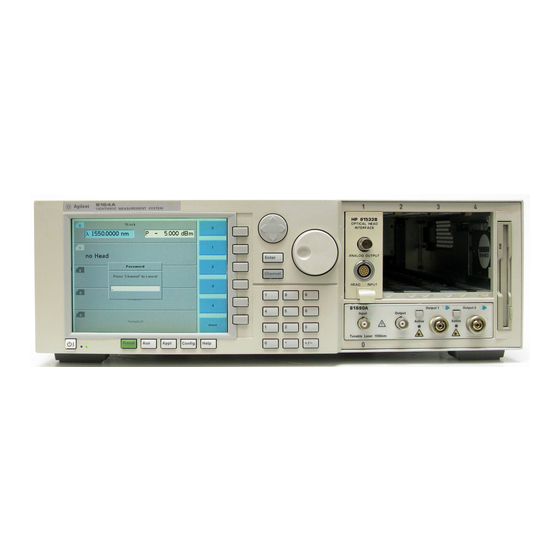
- Page 30 A Description of the User Interface 1.3 A Description of the User Interface Figure 1-3 and Figure 1-4 show the user interface of the HP 8164A and the HP 8163A, respectively, and the names used in this manual to describe the groups of keys.
- Page 31 Cursor Key Hardkeys Enter Channel Power Key Figure 1-4 The HP 8163A Lightwave Multimeter User Interface Password When you use this instrument with high-power Laser Source modules or Tunable Laser modules, you must enter the password to unlock the instrument.
- Page 32 The slot number represents the module’s position in the mainframe. Front-loadable modules are numbered from one to two from left to right for the HP 8163A and from one to four from left to right for the HP 8164A. These numbers are displayed on the front panel...
- Page 33 Getting Started A Description of the User Interface beside each module slot. The HP 8164A slot for back-loadable modules is numbered zero. N OT E The channel number of single channel modules is always one. How to Navigate/Modify the Display...
- Page 34 Getting Started A Description of the User Interface Figure 1-6 The HP 8164A’s Overview Screen How to Use the Cursor Key Figure 1-7 The Cursor Key You can move the highlighted marker between parameters using the [Cursor] hardkey.
- Page 35 How to Use the Numerical Keypad N OT E The Numerical Keypad is only available if you use the HP 8164A. You can use the Numerical Keypad to change the value of a parameter. See “How to Change the Value of a Parameter” on page 41.
- Page 36 C to select the channel and HANNEL pressing the [Details] softkey. You should see the Details screen as shown in Figure 1-9 or Figure 1-10. Figure 1-9 The HP 8163A’s Details Screen for a Power Sensor Channel...
- Page 37 Getting Started A Description of the User Interface Figure 1-10 The HP 8164A’s Details Screen for a Tunable Laser Channel To return to the overview screen press the [Overview] softkey.
- Page 38 Press the [Menu] softkey to access all the parameters of a module that can be changed. Figure 1-11 and Figure 1-12 show the type of menu you should see for a Power Sensor channel. Figure 1-11 The HP 8163A’s Menu for a Power Sensor Channel...
- Page 39 Getting Started A Description of the User Interface Figure 1-12 The HP 8164A’s Menu for a Power Sensor Channel How to Change the System Configuration Press the [Config] softkey to access all the system configuration parameters that can be changed. Figure 1-13 and Figure 1-14 show the menu you should see.
- Page 40 Getting Started A Description of the User Interface Figure 1-13 The HP 8163A System Configuration Menu...
-
Page 41: How To Change The Value Of A Parameter
Getting Started How to Change the Value of a Parameter Figure 1-14 The HP 8164A System Configuration Menu 1.4 How to Change the Value of a Parameter What follows is a description of the various ways of changing the value of parameters. Examples in which particular parameter values are changed are given with the parameter descriptions. -
Page 42: How To Select A Parameter
How to Make a Big Change to a Continuous Parameter If you are changing the value of a parameter completely, type in the value on the keypad (if you are using the HP 8164A), and press NTER To change the output power from 100 µW to 755 µW: 1 Press the [Menu] softkey. -
Page 43: How To Make A Small Change To A Continuous Parameter
Parameter For small changes to a parameter use the up and down cursor keys, the numerical keypad (if you are using the HP 8164A), or the modify knob (if you are using the HP 8164A). Move to the parameter and then: 1 Press [Edit]. -
Page 44: How To Change A Discrete Parameter
Getting Started How to Change the Value of a Parameter 5 When you have finished editing the value, press E . The NTER edited value becomes the new value of the parameter. To change the wavelength from 1540.000 nm to 1525.000 nm: 1 Move to the wavelength parameter for a Tunable Laser module and press [Edit]. -
Page 45: How To Set All Parameters To Their Default Values
Getting Started How to Change the Value of a Parameter Figure 1-16 Averaging Time Menu How to Set All Parameters to Their Default Values Press P to set all parameters to their default values. RESET If You Make a Mistake If you make a mistake while you are editing a parameter, you can cancel the editing, and retain the previous value for the parameter by pressing the [Cancel] softkey. -
Page 46: A Sample Session
This sample session shows you how to measure the power of a modulated signal at a single wavelength. The sample session is written for the HP 8163A Lightwave Multimeter or HP 8164A Lightwave Measurement System, the HP 81689A Tunable Laser module, and the HP 81532A Power Sensor. - Page 47 Getting Started A Sample Session Figure 1-17 Connecting the Instrument for the Sample Session 4 Make sure the instrument is powered up. 5 How to set the wavelength for the Power Sensor module: Move to the wavelength parameter, [λ], for the Power Sensor module and press E NTER Enter 1540.000 and press E...
- Page 48 Getting Started A Sample Session 8 How to set the wavelength for the Tunable Laser module: Move to the wavelength parameter, [λ], for the Tunable Laser module and press E NTER Enter 1540.000 and press E NTER 9 How to set the modulated power for the Tunable Laser module: If power is not displayed in Watts, move to the [P OWER parameter and press the [Power Unit] softkey.
- Page 49 Additional Features...
-
Page 50: Additional Features
Additional Features This chapter introduces addditional features of the HP 8163A Lightwave Multimeter and the HP 8164A Lightwave Measurement System. Here you will find out how to set the configuration settings and how to connect an external monitor. -
Page 51: Using The System Utilities
Other Functions Using the System Utilities This describes how to use the system functions of the HP 8163A Lightwave Measurement System and the HP 8164A Lightwave Measurement System. 2.1 Using the System Utilities Press the C hardkey to access configuration information for ONFIG your mainframe. -
Page 52: How To Set The Backlight & Contrast
TheContrast menu option allows you to set the appearance of the screen. NOT E The Contrast menu option is supported by the HP 8163A but not the HP 8164A. To Set the Contrast To change the contrast level of the HP 8163A’s screen:... -
Page 53: How To Set The Hp-Ib Address
Entering a Contrast Value 3 Enter an integer value between zero and one hundred in this box and press E NTER How to Set the HP-IB Address N OT E The default HP-IB address is 20. To set the HP-IB address: 1 Press the C hardkey. -
Page 54: How To Lock/Unlock The Instrument
Other Functions Using the System Utilities You see a box displaying the current HP-IB address. Figure 2-4 Entering a HP-IB Address 3 Enter an integer value between 0 and 30 into this box and press [Enter]. The address is set to this value. - Page 55 Other Functions Using the System Utilities Figure 2-5 Unlocking the Instrument 3 Enter the password, using the softkeys or the numerical keypad. Press E and the instrument unlocks. NTER N OT E The default password is 1234 . To lock the instrument, perform the steps above, but in step 2 move to the <...
-
Page 56: How To Change The Password
Other Functions Using the System Utilities How to Change the Password The password is used for unlocking the instrument. To change the password: 1 Press the C hardkey. ONFIG 2 Move to the <C > menu option and press HANGE ASSWORD . -
Page 57: How To Get Information About Modules
Other Functions Using the System Utilities To change the triggering mode: 1 Press the C hardkey. ONFIG 2 Move to the <T > menu option and press E . You see RIGGER NTER a box displaying the available triggering modes. Figure 2-6 Changing the Triggering Mode 3 Move to your chosen triggering mode and press E... -
Page 58: How To Get Information About The Mainframe
Other Functions Using the System Utilities 3 Press <Close> to return to the configuration menu. Figure 2-7 Viewing Information About Modules How to Get Information About the Mainframe To get information about the mainframe: 1 Press the C hardkey. ONFIG 2 Move to the <A >... -
Page 59: How To Connect An External Monitor
You can connect a standard VGA monitor to the HP 8164A Lightwave Measurement System. This is a useful feature for making presentations or for training courses. N OT E You cannot connect a monitor to the HP 8163A Lightwave Multimeter. - Page 60 Other Functions How to Connect an External Monitor Video Outlet Figure 2-9 Rear Panel of the HP 8164A Lightwave Measurement System • Place your monitor on a flat sturdy surface. • Before you make any connections make sure the Lightwave Measurement System and monitor are turned off.
- Page 61 Power Measurement...
-
Page 62: Power Measurement
Power Measurement This chapter explains how to measure optical power from the user interface of the HP 8163A Lightwave Multimeter and the HP 8164A Lightwave Measurement System. You may measure power using a Power Meter, that is: • a Power Sensor module or •... -
Page 63: How To Measure Power
Power Measurement How to Measure Power This chapter describes how to use the HP 8163A Lightwave Multimeter and the HP 8164A Lightwave Measurement System to measure optical power. 3.1 How to Measure Power The Power Value The <P> parameter displays the power measurement value. In MinMax mode, this parameter changes to <... -
Page 64: How To Set The Power Unit
Power Measurement How to Measure Power Figure 3-1 The Number of Digits Menu 3 Move to 2 and press E NTER 4 Press the [Close] softkey to exit the menu. How to Set the Power Unit Pressing the Power Unit softkey allows you to select either W, dB, or dBm as the units in which power is displayed. - Page 65 Power Measurement How to Measure Power You can also measure power in dB or dBm. Values displayed in these units are derived from measurement in Watts. By selecting dBm, the following calculation is made: input ------------------------------ - 3 – × 1 10 Where, is the power value displayed in dBm, and...
-
Page 66: How To Set The Calibration Offset
NTER How to Set the Calibration Offset This is a calibration offset that you can enter to compensate for external optical circuitry, for example, the HP 81022FF Integrating Sphere or a 3 dB coupler. The calibration offset, [C ], is automatically subtracted from the input signal. -
Page 67: How To Set The Reference Level
Power Measurement How to Measure Power is the input signal level , and input is the calibration offset. To set the calibration offset to 40.000 dB: 1 Move to the Power Meter channel and press the [Details] softkey. 2 Move to the [C ] parameter and press E NTER 3 Enter 40.000 and press E... -
Page 68: How To Set The Reference Value To The Current Power Value
Power Measurement How to Measure Power To set the reference level to 10 mW: 1 Move to the Power Meter channel and press the [Details] softkey. 2 Move to the [R ] parameter and press the [Power Unit] softkey. 3 Move to <W> and press E twice. - Page 69 Power Measurement How to Measure Power To reference another channel: 1 Move to the Power Meter channel and press the [Details] softkey. 2 Move to the [R ] parameter and press E NTER 3 Move to the channel number you want to reference, using the cursor key, and press Enter.
-
Page 70: How To Set The Wavelength
Power Measurement How to Measure Power How to Set the Wavelength This is the wavelength value. The responsivity of the Power Meter varies with wavelength. For accurate power measurement, you need to input the wavelength of the optical input. To set the wavelength to 1545.000 nm: 1 Move to the Power Meter channel and press the [Details] softkey. - Page 71 Power Measurement How to Measure Power Figure 3-4 Module Channels that are Settling 3 Move to the <Z > option to zero the current power measurement channel or the <Z > option to zero all power measurement channels. You will see the screen shown in Figure 3-5, this appears for around 30 seconds while zeroing is performed.
- Page 72 Power Measurement How to Measure Power Figure 3-5 Zeroing Screen NOT E If you see the screen shown in Figure 3-6, the zeroing operation has failed because the Power Meter received light. The most common reason for zeroing to fail is if •...
-
Page 73: How To Choose The Range Mode
Power Measurement How to Measure Power 4 When the zeroing operation finishes, press the [Close] softkey to close the menu. Figure 3-6 Zeroing Fails, if the Power Meter Receives Input Light. How to Choose the Range Mode You can choose either of two ranging modes from the Range mode menu: •... -
Page 74: How To Set The Range
Power Measurement How to Measure Power How to Set the Range If you choose <A > from the Range mode menu, this parameter can not be set. The Range parameter is displayed in light grey text, see Figure 3-7, in automatic ranging mode. Figure 3-7 Auto-Range Mode If you choose <M... - Page 75 Power Measurement How to Measure Power 4 Move to <dBm>, by using the cursor key, and press E NTER 5 Move to the [R ] parameter and press E ANGE NTER 6 Move to <A >, by using the cursor key, and press E NTER 7 Perform a set of measurements.
- Page 76 Power Measurement How to Measure Power Figure 3-8 Manual Range Mode - Within Range...
- Page 77 Power Measurement How to Measure Power If the measured power is more than 3dBm greater than the range setting, it is impossible for power to be displayed. The power value, +1.--- dBm, as shown in Figure 3-9, is shown. This means that the measured power is greater than the Upper Power Limit.
- Page 78 Power Measurement How to Measure Power If the measured power is more than 40 dBm less than the range setting, it is impossible for power to be displayed. The power value, -1.--- dBm, as shown in Figure 3-10, is shown. This means that the measured power is greater than the resolution at this [R ANGE value.
- Page 79 Power Measurement How to Measure Power Figure 3-11 shows the possible range values you can choose. These values range from 10 dBm (upper power limit of 13 dBm) to −70 dBm (upper power limit of −67 dBm) in 10 dBm increments. Figure 3-11 Range Value Menu...
-
Page 80: Upper Power Limit And Resolution
Power Measurement How to Measure Power Upper Power Limit and Resolution Table 3-1 shows the upper power limit and measurent resolution at various power ranges. As can be seen the resolution decreases as the chosen [R ] decreases. Resolution is always 40 dBm less ANGE than the chosen [R ] value. -
Page 81: How To Choose The Minmax Mode
Power Measurement How to Measure Power Measurements with Tavg ≤ 1 second Figure 3-1 With modules designed for the HP 8153A Lightwave Multimeter, for averaging times of more than 1 second, the displayed power is given by the formula: ... - Page 82 Power Measurement How to Measure Power principally for polarization dependent measurements, but can be used for other types of measurement. You can choose three modes of operation from the MinMax mode menu: • <C > mode, which compares each new measured ONTINUOUS value with the maximum and minimum values so far, and replaces them as necessary.
- Page 83 Power Measurement How to Measure Power N Samples Window Mode Time for display to update The length of the lines displayed represents the N Samples Reset size of the buffer at the Mode time of update Time for display to update Figure 3-2 The Window and Refresh Modes To choose the <R...
-
Page 84: How To Turn Off Minmax Mode
Power Measurement How to Measure Power Figure 3-3 MinMax Mode Screen 4 Press M , move to <D > and press E OINTS NTER 5 Enter 100 and press E NTER How to Turn Off MinMax Mode To turn off MinMax mode, and return to continuous power measurement: 1 Move to the Power Meter channel and press the [Details] softkey. -
Page 85: How To Hold The Screen
Power Measurement How to Measure Power How to Hold the Screen Pressing the [Hold/Cnt] softkey allows you to hold the screen so that no new measurements are displayed. Hold is displayed as shown in Figure 3-4, for the overview screen, and Figure 3-5, for the details screen. - Page 86 Power Measurement How to Measure Power Figure 3-5 Power Module Channel is Held - Details Screen By pressing the [Hold/Cnt] softkey a second time the screen will display new measurements continuously.
-
Page 87: Laser Sources
Laser Sources... - Page 88 Laser Sources This chapter explains how to control laser sources from the user interface of the HP 8163A Lightwave Multimeter and the HP 8164A Lightwave Measurement System.
-
Page 89: How To Use Laser Source Modules
Using Laser Source Modules How to Use Laser Source Modules This chapter describes how to use the HP 8163A Lightwave Multimeter and the HP 8164A Lightwave Measurement System to control fixed-wavelength laser source modules. 4.1 How to Use Laser Source Modules... -
Page 90: Dual-Wavelength Laser Source Modules
Using Laser Source Modules How to Use Laser Source Modules Dual-Wavelength Laser Source Modules Dual-wavelength laser source modules have optical outputs at two wavelengths. You can choose to output an optical signal at either a single wavelength or at both wavelengths simultaneously. To choose both output wavelengths for a dual-wavelength laser source module: 1 Move to [λ] parameter and press E... -
Page 91: How To Set Attenuation
Using Laser Source Modules How to Use Laser Source Modules 1 Move to [S ] parameter and press E TATE NTER 2 Move to [O ], by using the cursor key, and press E . The NTER green LED on the module front panel switches on. To disable laser output using the user interface: 1 Move to [S ] parameter and press E... -
Page 92: How To Modulate The Optical Output
Using Laser Source Modules How to Use Laser Source Modules 1 Move to the laser source channel and press the [Details] softkey. You see the screen in Figure 4-3. Figure 4-3 The Power Sensor Details Screen 2 Move to the [A ] parameter and press E TTENUATION NTER... -
Page 93: How To Modulate The Output Signal
> is displayed, the laser source outputs an unmodulated continuous-wave signal. N OT E If you choose to output both wavelengths of the HP 81554SM Dual Wavelength Laser Source and to modulate the optical output signal, the two signals will be 180° out of phase with each other. - Page 94 Using Laser Source Modules How to Use Laser Source Modules...
- Page 95 Tunable Lasers...
-
Page 96: Tunable Lasers
Tunable Lasers This chapter explains how to control Tunable Laser modules from the user interface of the HP 8163A Lightwave Multimeter and the HP 8164A Lightwave Measurement System. -
Page 97: What Is A Tunable Laser
Tunable Laser Sources What is a Tunable Laser ? 5.1 What is a Tunable Laser ? A tunable laser is a laser source for which the wavelength can be varied through a specified range. The Hewlett-Packard Tunable Laser modules also allow you to set the output power, and to choose between continuous wave or modulated power. -
Page 98: How To Set The Output Power Of A Cw Signal
Tunable Laser Sources How to Set the Power How to Set the Output Power of a CW Signal How to Set Output Power To set the output power to 555.000 µW: Atten u a to r If your tunable laser has an in-built optical attenuator, move to ], press E , move to <A >, and press E... - Page 99 Tunable Laser Sources How to Set the Power Figure 5-1 Setting High Power parameters...
- Page 100 Tunable Laser Sources How to Set the Power Figure 5-2 Setting Low SSE parameter NOT E If you select <B :2)> or <B :1)> as the MASTER MASTER regulated path, both channels output optical power. You can only view or set the parameters for the primary optical output, for example, the high power output for <B :2)>.
-
Page 101: How To Set The Optical Output
Tunable Laser Sources How to Set the Power How to Set the Optical Output 1 Move to [O ] and press E UTPUT NTER 2 Move to your chosen optical output and press E NTER How to Enable the Optical Output 3 Move to [S ] and press E TATE... -
Page 102: How To Set Power And Attenuation
Tunable Laser Sources How to Set the Power How to Set Power and Attenuation Atten u a to r If your tunable laser has an in-built optical attenuator, you can set the laser output power and then set the attenuation. 1 Move to the Tunable Laser channel and press [Details]. - Page 103 Tunable Laser Sources How to Set the Power Figure 5-3 Setting Attenuation...
-
Page 104: What Is Excessive Power
Tunable Laser Sources How to Set the Power What is Excessive Power ? If the text ExP is displayed in a Tunable Laser channel, see Figure 5-4, you have set an output power level that is larger than the laser diode can produce at the selected wavelength. -
Page 105: The Analog Output
Tunable Laser Sources How to Set the Power The Analog Output If there is an output BNC connector on the front panel of your Tunable Laser module, you can output a DC voltage level that is proportional to the laser output power. The relationship between this voltage level and the output power is not calibrated. -
Page 106: Output
You can set a wavelength range for the instrument to “sweep”. Wavelength Range Every Tunable Laser module has a specified wavelength range. This range is available for all Tunable Laser modules. See Appendix C of the HP 81640A/80A/82A/89A Tunable Laser modules User’s Guide to find your module’s specified range. -
Page 107: How To Set The Wavelength Directly
Tunable Laser Sources How to Set the Wavelength Every Tunable Laser module has a permitted wavelength range. This range is greater than the specified range. The permitted wavelength range varies for each Tunable Laser module. You can set the wavelength to any value within the permitted wavelength range. -
Page 108: How To Change The Output Wavelength
Tunable Laser Sources How to Set the Wavelength cλ λ ------------------------- - λ To set a frequency offset of 1.000 THz from a base wavelength of 1545 nm: 1 Move to the Tunable Laser channel and press [Details]. 2 Press [Menu]. The menu appears. 3 Move to <W >... -
Page 109: How To Set The Base Wavelength
Tunable Laser Sources How to Perform a Wavelength Sweep 6 Enter 1570 and press E NTER N OT E Note how the frequency offset, [ f], changes as you change the value of ∆ [λ]. How to Set the Base Wavelength N OT E You cannot set <λ0>, the base wavelength directly. -
Page 110: How To Set The Wavelength Sweep
Tunable Laser Sources How to Perform a Wavelength Sweep How to Set the Wavelength Sweep The Sweep Parameters These are the parameters for the wavelength sweep: [λ S • ], the wavelength at which the sweep begins, TART [λ S •... -
Page 111: How To Set The Maximum Power For The Sweep Range
Tunable Laser Sources How to Perform a Wavelength Sweep Figure 5-9 illustrates how these modes work for a three-cycle wavelength sweep. <T > <O > WOWAY NEWAY λ λ λ Stop λ Stop λ Start λ Start Figure 5-9 Repeat Modes How to Set the Maximum Power for the Sweep Range Pressing [Pmax/Swp] sets the power to the maximum for the selected sweep range. -
Page 112: How To Execute A Stepped Sweep
Tunable Laser Sources How to Perform a Wavelength Sweep How to Execute a Stepped Sweep To execute a stepped wavelength sweep over the range 1510 nm to 1570 nm, three times, sweeping two ways, in 1 nm steps, stopping for half a second at each wavelength step: 1 Move to the Tunable Laser channel and press [Details]. - Page 113 Tunable Laser Sources How to Perform a Wavelength Sweep Figure 5-10 Executing a Stepped Sweep...
-
Page 114: How To Execute A Continuous Sweep
Tunable Laser Sources How to Perform a Wavelength Sweep Figure 5-11 Pausing a Stepped Sweep How to Execute a Continuous Sweep You cannot choose a repeat mode for a continuous sweep. All multi-cycle sweeps are one-directional, see Figure 5-9. To execute a continuous wavelength sweep over the range 1520 nm to 1560 nm, three times, at a speed of 5 nm/s: 1 Move to the Tunable Laser channel and press [Details]. -
Page 115: How To Perform A Manual Sweep
Tunable Laser Sources How to Perform a Wavelength Sweep 8 Move to [S ] and press E WEEP YCLES NTER 9 Enter 0003 and press E NTER 10 Move to [V ] and press E SWEEP NTER 11 Move to 5 nm/s, by using the cursor key, and press E NTER 12 Press [Run Swp] to start the sweep. -
Page 116: How To Modulate A Signal
Tunable Laser Sources How to Modulate a Signal Figure 5-12 Performing a Manual Sweep 7 Perform step 6 until you choose to press [Stop]. 5.5 How to Modulate a Signal There are two ways of modulating the amplitude of the optical output. -
Page 117: How To Use The Internal Modulation
Tunable Laser Sources How to Modulate a Signal How to Use the Internal Modulation The internal modulation is a square wave with a 50% duty cycle. You can set both the amplitude and the frequency of this signal. The amplitude is set by the power parameter. This is the maximum output power of the output signal;... -
Page 118: How To Use External Modulation
HP 81682A, and HP 81640A - a BNC input connector and a BNC output connector. There is one BNC connector on the front panel of the HP 81689A - a BNC input connector. An absolute maximum of ±6 V can be applied as an external voltage to any of these BNC connector. -
Page 119: External Analog Modulation
HP 81682A, and HP 81640A - a BNC input connector and a BNC output connector. There is one BNC connector on the front panel of the HP 81689A - a BNC input connector. An absolute maximum of ±6 V can be applied as an external voltage to any... -
Page 120: Wavelength Locking
Tunable Laser Sources How to Modulate a Signal Analog Input ±15% Output Power Figure 5-15 External Analog Modulation and Output Power To enable external analog modulation: 1 Move to the Tunable Laser channel and press [Details]. 2 Move to [M ] and press E NTER 3 Move to <E... -
Page 121: External Digital Modulation Using Input Trigger Connector
C AU T ION There are two BNC connectors on the front panel of the HP 81680A, HP 81682A, and HP 81640A - a BNC input connector and a BNC output connector. An absolute maximum of ± 6 V can be applied as an external voltage to any BNC connector. -
Page 122: How To Increase Linewidth
HP 81689A Tunable Laser module behaves differently from all other modules. If the duty cycle varies: • the average power of the output signal of the HP 81689A Tunable Laser module varies in proportion with the change in duty cycle, while, •... -
Page 123: How To Set The Output Power Of A Modulated Signal
Tunable Laser Sources How to Modulate a Signal Coherence control greatly reduces interference effects and therefore improves the power stability in sensitive test setups. To enable coherence control: 1 Move to the Tunable Laser channel and press [Details]. 2 Move to [M ] and press E NTER 3 Move to <C... -
Page 124: How To Use Triggers
How to Use Input Triggering You can configure your HP 81689A Tunable Laser module to perform certain tasks when you apply a trigger to the Input Trigger Connector. CAUT IO N A maximum of 5 V can be applied as an external voltage to the Input Trigger connector, see page 152. -
Page 125: How To Use Output Triggering
Tunable Laser Sources How to Use Triggers 3 Move to <I >, by using the cursor key, and NPUT RIGGER press E . You will see the screen in Figure 5-17. NTER Figure 5-17 Input Trigger Mode 4 Move to one of the following, by using the cursor key: •... - Page 126 Tunable Laser Sources How to Use Triggers 1 See “How to Set the Trigger Configuration” on page 56 for how to configure the trigger connectors. 2 Move to the Tunable Laser channel and press [Menu]. 3 Move to <O >, by using the cursor key, UTPUT RIGGER and press E...
-
Page 127: How To Use Auxiliary Functions
Tunable Laser Sources How to Use Auxiliary Functions 5.7 How to Use Auxiliary Functions Automatic Realignment Automatic Realignment realigns the laser cavity after Laser Protection. You should use Automatic Realignment if you have already tried to reactivate the laser and to reduce power, and this has been unsuccessful. -
Page 128: How To Perform A Wavelength Zero
Tunable Laser Sources How to Use Auxiliary Functions Figure 5-19 Realign Screen How to Perform a Wavelength Zero Performing a Wavelength Zero recalibrates the optical wavelength. This wavelength may drift due to a change in temperature and other environmental conditions. A Wavelength Zero is automatically performed when the instrument boots or when an Automatic Realignment is performed. - Page 129 Tunable Laser Sources How to Use Auxiliary Functions λ Zero Screen Figure 5-20 3 Wait several minutes. This time depends on how much the wavelength of the instrument has drifted since the last Wavelength Zero was performed. N OT E The instrument automatically performs a Wavelength Zero if there is a ±...
- Page 130 Tunable Laser Sources How to Use Auxiliary Functions...
-
Page 131: A Installation And Maintenance
Installation and Maintenance... - Page 132 Installation and Maintenance This appendix provides installation instructions for the HP 8163A Lightwave Multimeter and the HP 8164A Lightwave Measurement System. It also includes information about initial inspection and damage claims, preparation for use, packaging, storage, and shipment.
-
Page 133: Safety Considerations
Appendix A. Installation and Maintenance Safety Considerations A.1 Safety Considerations The HP 8163A Lightwave Multimeter and the HP 8164A Lightwave Measurement System are Safety Class 1 instruments (that is, instruments with a metal chassis directly connected to earth via the power supply cable). The shown symbol is used to show a protective earth terminal in the instrument. -
Page 134: Ac Line Power Supply Requirements
(covers, panels, and so on). A.3 AC Line Power Supply Requirements The HP 8163A Lightwave Multimeter can operate from the single- phase AC power source that supplies between 100 V and 240 V at a frequency in the range 50 to 60 Hz. The maximum power consumption is 120 VA with all options installed. - Page 135 AC Line Power Supply Requirements C AU TI O N Please note that the power key on the front panel of the HP 8164A Lightwave Measurement System does not stop the flow of power to the instrument. The power key allows you to switch between stand-by mode and power-on mode.
- Page 136 Appendix A. Installation and Maintenance AC Line Power Supply Requirements NOT E You only need to use the line power cable to connect to the AC adapter. Figure A-2 Line Power Cables – Plug Identification WAR NI NG To avoid the possibility of injury or death, you must observe the following precautions before switching on the instrument.
-
Page 137: Changing The Battery
Figure A-3 AC Power Requirement Markings - HP 8163A Figure A-4 AC Power Requirement Markings - HP 8164A Changing the Battery The HP 8163A Lightwave Multimeter and the HP 8164A Lightwave Measurement System contain a lithium thionyl chloride... -
Page 138: Changing The Fuse
Changing the battery should be carried out only by HP service personnel. If you need to get the battery replaced refer to your nearest Hewlett-Packard Sales/Service Office. -
Page 139: Temperature
Humidity The operating humidity for the HP 8164A Lightwave Measurement System is < 80% from 10° C to +35° C. The operating humidity for the HP 8163A Lightwave Multimeter is up to 95% from 0°C to +40°C. Storage and Shipment The instrument can be stored or shipped at temperatures between -40°C and +70°C. -
Page 140: Operating Position
Operating and Storage Environment Operating Position When operating the HP 8163A or the HP 8164A, choose a location that provides at least 75 mm (3 inches) of clearance at the rear, and at least 25 mm (1 inch) of clearance at each side. Failure to provide adequate air clearance may result in excessive internal temperature, reducing instrument reliability. -
Page 141: Storage Position
Operating and Storage Environment Storage Position The HP 8164A Lightwave Measurement System can be stored in its operating position, as shown in Figure A-5, or on its back legs as shown in Figure A-7. The back legs protect the connectors on the back panel from damage. -
Page 142: Carrying The Instrument
Appendix A. Installation and Maintenance Operating and Storage Environment Figure A-7 Storing the HP 8164A on its Back Legs. Carrying the Instrument When carrrying the HP 8164A Lightwave Measurement System, grip the strap at the side of the instrument as shown in Figure A-8. -
Page 143: Using Modules
• Front-loadable modules - these modules fit in the four module slots at the front of the HP 8164A Lightwave Measurement System or the two module slots at the front of the HP 8163A Lightwave Multimeter. • Back-loadable modules - these tunable laser source modules fit in the large module slot at the rear of the HP 8164A Lightwave Measurement System. -
Page 144: How To Remove A Front-Loadable Module
Make sure that the line power is switched off before you remove a module. Figure A-9 How to Remove a Front-Loadable Module from the HP 8163A 1 Lift the catch at the bottom front of the module. 2 With the catch lifted, pull the module out of the instrument. If the module does not slide out freely, check that you have lifted the catch high enough. -
Page 145: How To Fit A Front-Loadable Module
Make sure that the line power is switched off before you fit a module. Figure A-10 How to Insert a Front-Loadable Module into the HP 8163A 1 Position the module at an unoccupied slot, with the catch at the bottom front of the module. -
Page 146: How To Remove A Back-Loadable Module
1 Untighten the retaining screws, see Figure A-11, that secure the module in the instrument. Retaining Screws Handle Figure A-11 Back Panel of HP 8164A Lightwave Measurement System Retaining Screws Figure A-12 Side View of a Back-Loadable Module 2 Pull the module out of the mainframe, using the handle, being... - Page 147 Figure A-13 Removing a Back-Loadable Module from the HP 8164A C AU TI O N If you pull the module out at an angle or vertically, you may damage the instrument and the module. You should pull the module out along the...
-
Page 148: How To Fit A Back-Loadable Module
Appendix A. Installation and Maintenance Using Modules How to Fit a Back-Loadable Module CAU TI O N Disconnect all electrical and optical connectors before you fit this module into the instrument, as this can cause damage to the connectors. Make sure that the instrument is in stand-by mode, see page 135, before you remove a module. -
Page 149: Adding A Connector Interface
Appendix A. Installation and Maintenance Using Modules careful to keep the module completely flat. If the module does not slide freely, check that you have correctly oriented it and that there is no obstruction to its movement. C AU TI O N If you insert the module at an angle or vertically, you may damage the instrument and the module. -
Page 150: Protecting Empty Module Slots
• prevent dust pollution and • optimize cooling by guiding the air flow. Fitting Blind Panels for Front-Loadable Module Slots To fit the HP 08163-40199 Blind Panel, follow the following procedure. 1 Position the blind panel as shown in Figure A-16. Position the end closest to the handle against the bottom edge of the slot. -
Page 151: Fitting A Filler Module For Back-Loadable Module
The HP 81645A Filler Module must be used if you have not installed a back-loadable Tunable Laser module into the HP 8164A Lightwave Measurement System. The HP 81645A Filler Module can be fitted in the same way as any back-loadable module, see “How to Fit a Back-Loadable Module” on page 148. -
Page 152: Input And Output Connectors
Appendix A. Installation and Maintenance Input and Output Connectors A.6 Input and Output Connectors There are three BNC connectors on the rear panel of the HP 8163A Lightwave Multimeter and of the HP 8164A Lightwave Measurement System. These are the Remote Interlock, the Trigger Out and the Trigger In connectors. -
Page 153: Hp-Ib Interface
Setting the trigger configuration is explained in Chapter 2. A.7 HP-IB Interface You can connect your HP-IB interface into a star network, a linear network, or a combination star and linear network. The limitations imposed on this network are as follows: •... -
Page 154: Cables And Adapters
• HP-IB Cable, 10833C, 4 m (13.2 ft.) • HP-IB Cable, 10833D, 0.5 m (1.6 ft.) • HP-IB Adapter, 10834A, 2.3 cm. extender. Use this adapter if there is no space to connect your HP-IB cable directly to a HP-IB interface. Connector The following figure shows the connector and pin assignments. -
Page 155: Hp-Ib Logic Levels
• True = Low = digital ground or 0 Vdc to 0.4 Vdc • False = High = open or 2.5 Vdc to 5 Vdc All HP-IB lines have LOW assertion states. High states are held at 3.0 Vdc by pull-ups within the instrument. When a line functions as an input, it requires approximately 3.2 mA to pull it low through a... -
Page 156: Claims And Repackaging
Service Office will arrange for repair or replacement of the unit without waiting for settlement of the claim against the carrier. Return Shipments to HP If the instrument is to be shipped to a Hewlett-Packard Sales/ Service Office, attach a tag showing owner, return address, model number and full serial number and the type of service required. -
Page 157: Hewlett-Packard Sales And Service Offices
For more information about Hewlett-Packard test and measurement products, applications, services, and for a current sales office listing, visit our web site: http://www.hp.com/go/tmdir. You can also contact one of the following centers and ask for a test and measurement sales representative. -
Page 158: Latin America
Appendix A. Installation and Maintenance Claims and Repackaging Latin America Hewlett-Packard Company Latin American Region Headquarters 5200 Blue Lagoon Drive 9th Floor Miami, Florida 33126, U.S.A. (tel) (305) 267 4245/4220 (fax) (305) 267 4288 Australia/New Zealand Hewlett-Packard Australia Ltd. 31-41 Joseph Street Blackburn, Victoria 3130 Australia (tel) 1 800 629 485 (Australia) (tel) 0 800 738 378 (New Zealand) - Page 159 Accessories...
- Page 160 Accessories The HP 8163A Lightwave Multimeter and the HP 8164A Lightwave Measurement System are available in various configurations for the best possible match to the most common applications. This appendix provides information on the available options and accessories.
-
Page 161: Instrument And Options - Hp 8163A
Description HP 8163A Lightwave Multimeter Mainframe Modules The HP 8163A Lightwave Multimeter can be used with the following module in addition to all the modules listed in “HP 8153A Lightwave Multimeter Modules” on page 164. Tunable Laser Source Module Model No. -
Page 162: Instrument And Options - Hp 8164A
Model No. Description HP 81680A Tunable Laser for the Test of Critical dense-WDM Components HP 81682A Tunable Laser for the Test of Optical Amplifiers and Passive Components HP 81689A Tunable Laser for Multi-Channel Test Applications HP 81640A Tunable Laser for the Test of Critical Components in both... -
Page 163: Options
The HP 81640A/80A Tunable Laser Source Modules have a built-in optical attenuator as standard for Output 2, the High Power output. A built-in optical attenuator is not available for the HP 81689A. Option 021 - HP 81689A Standard single mode fiber, for straight contact connectors. -
Page 164: User's Guides
Lightwave Measurement System support the use of all modules designed for the HP 8153A Lightwave Multimeter except the HP 81534A Return Loss Module, which may be supported by later firmware releases. See Chapters 3, 4, and 5 to find out how to use these modules from... - Page 165 HP 8153A Lightwave Multimeter Modules Optical Heads Model No. Description HP 81520A Si, +10 to −100 dBm, 450 to 1020 nm Ge, +3 to −80 dBm, 900 to 1700 nm HP 81521B Opt 001 0.003 dB polarization stability, +3 to −64 dBm HP 81524A InGaAs, +3 to −90 dBm, 800 to 1650 nm...
-
Page 166: Hp-Ib Cables And Adapters
• HP-IB Cable, 10833C, 4 m (13.2 feet) • HP-IB Cable, 10833D, 0.5 m (1.6 feet) • HP-IB Adapter, 10834A, 2.3 cm extender. Use this adapter if there is no space to connect your HP-IB cable directly to a HP-IB interface. - Page 167 Specifications...
- Page 168 Specifications The HP 8163A Lightwave Multimeter and the HP 8164A Lightwave Measurement System are produced to the ISO 9001 international quality system standard as part of HP’s commitment to continually increasing customer satisfaction through improved quality control. Specifications describe the instrument’s warranted performance.
-
Page 169: Hp 8163A Specifications
Appendix C. Specifications HP 8163A Specifications C.1 HP 8163A Specifications The HP 8163A Lightwave Multimeter has a dual channel display. Graphical display 190 × 300 points visible, Display monochrome. The HP 8163A mainframe supports all modules Compatibility with HP 8153A... -
Page 170: Hp 8164A Specifications
The HP 8164A mainframe supports all modules Compatibility with HP 8153A from the HP 8153A Lightwave Multimeter, apart Lightwave Multimeter Modules from the HP 81534A Return Loss Module . Data Acquisitions Memory 4000 measurement results / channel min 100 µs or 10 ms, depending on sensor module... - Page 171 HP-IB interface Function code SH1, AH1, T6, L4, SR1, RL1, PP0, DC2, DT0, C0. SCPI standard; HP 8153A code compatibility HP-IB capability All modes and parameters accessible via HP-IB interface RS232C Interface: max. baud rate 115200 bps Centronics Parallel Printer Interface...
-
Page 172: Declaration Of Conformity
The product also conforms to other standards not listed here. If you need further information on conformance to a particular standard, please contact your local Hewlett-Packard Sales and Service Office. The product was tested in a typical configuration with HP systems (Type test). -
Page 173: Hp 8164A Lightwave Measurement System
Appendix C. Specifications Declaration of Conformity The FDA Accession Number 9122175-06 Böblingen, 29 April, 1999 Wolfgang Fenske OCM Regulations Consultant HP 8164A Lightwave Measurement System Manufacturer: Hewlett-Packard GmbH Optical Communication Measurement Herrenberger Strasse 110-140 D-71034 Böblingen Germany We declare that the system:... -
Page 174: Supplementary Information
The product also conforms to other standards not listed here. If you need further information on conformance to a particular standard, please contact your local Hewlett-Packard Sales and Service Office. The product was tested in a typical configuration with HP systems (Type test). The FDA Accession Number 9122175-06 Böblingen, 29 April, 1999... -
Page 175: D Performance Tests
Performance Tests... - Page 176 Performance Tests These Performance Tests test the functionality of the instrument. The HP 8163A Lightwave Multimeter and the HP 8164A Lightwave Measurement System comprises a power supply, a CPU, a hard-disk drive, and a display. The HP 8164A Lightwave Measurement System also has a floppy-disk drive.
-
Page 177: Equipment Required
(or HP81520A, HP 81521B, HP 81525A) HP 81682A Tunable Laser Module HP 81680A, HP 81640A 2 x HP 81000AI Connector Adapter (Head) Any other HP interface or HP adapter, dependent on patchcord HP 81101AC Singlemode Fiber Any other HP patchcord Test Record Results of the Performance Test may be tabulated in the Test Record provided after the test procedures. -
Page 178: Test Failure
Performance Tests Test Failure If the HP 8163A Lightwave Multimeter or the HP 8164A Lightwave Measurement System fail any Performance Test, return the instrument to the nearest Hewlett-Packard Sales/Service Office for repair. Instruments Specifications Specifications are the characteristics of the instrument that are certified. -
Page 179: Performance Test Instructions
1 Setup the test equipment as shown in Figure D-1: Insert the fixed laser source module in slot 1 and the power sensor in slot 2. If you use the HP 8164A Lightwave Measurement System, insert the back-loadable Tunable Laser module, if available, in slot 0. -
Page 180: Testing The Softkeys And The Cursor Key
14 Press [Menu]. The menu should appear. 15 Press [Close]. The menu should disappear. 16 Press [Details]. The details screen should appear. You should see the [Cal], [Ref], and [Range] parameters in addition to [P] and [λ]. If you use the HP 8164A Lightwave Measurement System,... -
Page 181: Testing The The Modify Knob
Overview Screen showing all channels should appear. Testing the the Modify Knob N OT E The Modify Knob is only available if you use the HP 8164A. 23 Turn the Modify Knob clockwise. Check the fields on the display being highlighted one after another. -
Page 182: Testing The Number Keys
1 Setup the test equipment as shown in Figure D-1: Insert the fixed laser source module in slot 1 and the power sensor in slot 2 . If you use the HP 8164A Lightwave Measurement System, insert the back-loadable Tunable Laser module, if available, in slot 0. -
Page 183: Test Of The Tunable Laser Module Channel (Slot 0)
8 Note the power reading of the power sensor in the test record. The Module Interaction Test ends here if you use the HP 8163A. N OT E If you use the HP 8164A, perform steps 9 to 12. -
Page 184: Hp-Ib Interface Test (Optional)
You will need a controller/computer with HP-IB capabilities for this test. 1 Connect the HP 8163A Lightwave Multimeter or the HP 8164A Lightwave Measurement System to the controller via the HP-IB. 2 Switch on the instrument and wait until it has booted. -
Page 185: Test Record
Performance Tests Test Record D.2 Test Record HP 8163A Lightwave Multimeter Performance Test Page 1 of 3 Model HP 8163A Lightwave Multimeter Date _________ Serial No. ________________________ Ambient Temperature _________°C Options ________________________ Relative Humidity _________% Firmware Rev. ________________________ Line Frequency... - Page 186 Performance Tests Test Record HP 8163A Lightwave Multimeter Performance Test Page 2 of 3 HP 8163A Serial No.__________ Trace No.__________ Date__________ Test Equipment Used Description Model No. Trace No Cal. Due Date CW Laser Source ___________ ___________ ___________ Optical Power Sensor...
- Page 187 Performance Tests Test Record HP 8163A Lightwave Multimeter Performance Test Page 3 of 3 HP 8163A Serial No.__________ Trace No.__________ Date__________ Display / Key Performance Test Check Passed/Failed as appropriate Passed Failed Test of the Hardkeys: ______ ______ Test of the Cursorkey and the E...
- Page 188 Performance Tests Test Record...
- Page 189 Performance Tests Test Record HP 8164A Lightwave Measurement System Performance Test Page 1 of 3 Model HP 8164A Lightwave Measurement Date _________ System Serial No. ________________________ Ambient Temperature _________°C Options ________________________ Relative Humidity _________% Firmware Rev. ________________________ Line Frequency _________Hz...
- Page 190 Performance Tests Test Record HP 8164A Lightwave Measurement System Performance Test Page 2 of 3 HP 8164A Serial No.__________ Trace No.__________ Date__________ Test Equipment Used Description Model No. Trace No Cal. Due Date CW Laser Source ___________ ___________ ___________ Optical Power Sensor...
- Page 191 Test of Slot 0 (Optional): −16 dBm − 4 dBm Use of HP 81680A: _____ ______ ______ Use of HP 81682A, standard: − 6 dBm _____ + 6 dBm ______ ______ −16 dBm − 4 dBm Use of HP 81682A, #003:...
- Page 192 Performance Tests Test Record...
-
Page 193: E Cleaning Procedures
Cleaning Procedures... - Page 194 Cleaning Procedures In general, whenever possible use physically contacting connectors, and dry connections. Fiber connectors may be used dry or wet. Dry means without index matching compound. Clean the connectors, interfaces and bushings carefully each time after use. WA RN IN G Make sure to disable all sources when you are cleaning any optical interfaces.
-
Page 195: Cleaning Materials
9300-1351 Blow Brush 9300-1131 Adhesive Cleaning tape 15475-68701 Isopropyl Alcohol Not available from HP. This should be available from any local pharmaceutical supplier. Pipe Cleaner WARN IN G To prevent electrical shock, disconnect the Lightwave Measurement System from the mains before cleaning. Use a dry cloth or one slightly dampened with water to clean the external case parts. -
Page 196: Cleaning Fiber/Panel Connectors
Appendix E. Cleaning Procedures Cleaning Fiber/Panel Connectors E.3 Cleaning Fiber/Panel Connectors 1 To clean the instrument panel connector remove the connector interface. 2 Apply some isopropyl alcohol to the lens cleaning paper and clean the surface and the ferrule of the connectors. 3 Using a new dry piece of cleaning paper, wipe the connector surface and ferrule until they are dry and clean. -
Page 197: Cleaning Connector Bushings
NEVER use any index matching compound, cleaning fluid or cleaning spray. E.6 Cleaning Detector Windows As used on the HP 81520A and HP 81521B Optical Heads (large area). 1 Use the blow brush to remove any particles from the surface. -
Page 198: Cleaning Detector Lens Interfaces
Appendix E. Cleaning Procedures Cleaning Detector Lens Interfaces E.8 Cleaning Detector Lens Interfaces As used on the HP 81522A Optical Head (small area) and HP 8140A and HP 8153A detector modules. Normally, the lens interface can be cleaned by using the blow brush. -
Page 199: F Firmware Updates
Firmware Updates... - Page 200 Firmware Updates This appendix provides information about the firmware update process for the HP 8163A Lightwave Multimeter and the HP 8164A Lightwave Measurement System.
- Page 201 You can choose to receive the Firmware Update on: • a CD-ROM containing in addition to the Firmware Update itself, the latest User’s Guides and the latest HP 816x VXIplug&play Instrument Driver or • a set of floppy disks containing the Firmware Update alone.
- Page 202 Firmware Update Process Our Address is: OCM Marketing Hewlett-Packard GmbH Herrenberger Strasse 130-140 71034 Boeblingen GERMANY You purchase HP 8164A or HP 8163A with firmware revision 1.0 preinstalled Information on getting firmware updates is contained in the User’s Guide and on the...
- Page 203 F. Firmware Updates Firmware Update Process How to Update Firmware You can receive a firmware update on the following media: • as a download from the internet, • on CD-ROM, or • on floppy disks. How to Update Firmware from the Internet You can download the firmware update from the Internet as a self- extracting file.
- Page 204 F. Firmware Updates Firmware Update Process...
- Page 205 ..127 ......138 Auxiliary Functions Fuse ....196 cleaning automatic realignment ....52 Contrast ...128 wavelength zero ....14 Conventions ....139 Cooling ....27 HP 8163A ....28 HP 8164A ....52 Backlight HP-IB ..109 Base Wavelength .....53 Address ......65 ....137 Battery Cables and Adapters ......65 ....153...
- Page 206 Index ..91 ..169 . 54 Lock the instrument laser sources HP 8163A ..63 ..170 power meters HP 8164A ..97 tunable lasers Storage and Shipment ..... 135 Power Key Storage environment ..141 Power Measurement Storage Position ..
- Page 207 Index ....97 power relative wavelength ...124 triggering Zeroing Electrical Offsets ..106 wavelength wavelength locking .108 wavelength mode ...128 wavelength zero Unlock the Instrument ..30 User Interface ...36 channel hardkey ..39 config softkey ..34 cursor key ..36 details screen .....32 features ....32 hardkeys ..38...
Need help?
Do you have a question about the 8163A and is the answer not in the manual?
Questions and answers