MacDon PW8 Operator's Manual
Pick-up header
Hide thumbs
Also See for PW8:
- Operator's manual (304 pages) ,
- Unloading and assembly instructions (170 pages) ,
- Unloading and assembly instructions (146 pages)

Related Manuals for MacDon PW8


Summary of Contents for MacDon PW8
- Page 1 Pick-Up Header Operator’s Manual 215575 Revision B Original Instruction The Harvesting Specialists.
- Page 2 © 2021 MacDon Industries, Ltd. The information in this publication is based on the information available and in effect at the time of printing. MacDon Industries, Ltd. makes no representation or warranty of any kind, whether expressed or implied, with respect to the information in this publication.
- Page 3 Declaration of Conformity 215575 Revision B...
- Page 4 215575 Revision B...
- Page 5 Introduction The MacDon PW8 Pick-Up Headeris designed to pick up windrows and feed them into a combine. This manual contains operating and maintenance procedures for the pick-up header for the following combines: Combine Model Case IH 50/60/7088, 51/61/7130, 51/61/7140, 70/8010, 71/81/9120, 72/82/9230, and 72/82/9240 ®...
- Page 6 Keep this manual handy for frequent reference and to pass on to new Operators or Owners. The PW8 Pick-Up Header Parts Catalog also is supplied with your new header. Call your Dealer if you need assistance, information, or additional copies of the manuals.
-
Page 7: Summary Of Changes
Internal Use Summary of Change Section Only Technical 1.7 Safety Sign Locations, page 8 Removed all non-MacDon illustrations. Publications 3.10 Header Attachment and Removed all instructions referencing shipping braces from all sub- Technical Detachment, page 38 topics in this section. -
Page 8: Serial Number
Serial Number Serial number plate (A) is located on the left endsheet. Record the serial number of your MacDon PW8 Pick-Up Header here: ____________________________________________ Figure 2: Left Side — Rear View 215575 Revision B... -
Page 9: Table Of Contents
TABLE OF CONTENTS Declaration of Conformity ..........................i Introduction ..............................i Summary of Changes........................... iii Serial Number............................iv Chapter 1: Safety ............................1 1.1 Safety Alert Symbols ..........................1 1.2 Signal Words ............................2 1.3 General Safety ............................3 1.4 Maintenance Safety ..........................5 1.5 Hydraulic Safety .............................6 1.6 Safety Signs ............................7 1.6.1 Installing Safety Decals........................7 1.7 Safety Sign Locations..........................8... - Page 10 TABLE OF CONTENTS 3.10.2 Case IH ............................. 44 Attaching Header to Case IH Combine .................... 44 Detaching Header from Case IH Combine..................47 3.10.3 Challenger®, Gleaner®, and Massey Ferguson® ................50 Attaching Header to Challenger®, Gleaner®, and Massey Ferguson® Combines........51 Detaching Header from Challenger®, Gleaner®, and Massey Ferguson®...
- Page 11 TABLE OF CONTENTS 4.3.1 Removing Header Height Sensor Assembly — Left Side..............105 4.3.2 Installing Header Height Sensor Assembly — Left Side ..............106 4.3.3 Removing Header Height Control System — Right Side ..............107 4.3.4 Installing Header Height Sensor Assembly — Right Side ..............109 4.4 Height Sensor Output Voltage Range –...
- Page 12 TABLE OF CONTENTS 4.9.8 Troubleshooting Alarms and Diagnostic Faults – Gleaner ® R65/R66/R75/R76 and S Series ...... 159 ® 4.10 Gleaner S9 Series Combines ......................161 4.10.1 Setting up the Header – Gleaner ® S9 Series .................. 161 4.10.2 Setting up Automatic Header Controls – Gleaner ®...
- Page 13 TABLE OF CONTENTS Chapter 5: Maintenance and Servicing....................215 5.1 Preparing Header for Servicing......................215 5.2 Maintenance Requirements ......................... 216 5.2.1 Maintenance Schedule/Record ..................... 216 5.2.2 Preseason/Annual Service ......................218 5.2.3 End-of-Season Service......................... 219 5.3 Lubrication ............................220 5.3.1 Greasing Procedure ........................220 5.3.2 Greasing Points .........................
- Page 14 TABLE OF CONTENTS Replacing Drive Roller Bearing on Right Side of Rear Deck..............274 Replacing Idler Roller Bearing on Left Side of Rear Deck ..............278 Replacing Idler Roller Bearing on Right Side of Rear Deck ..............279 Aligning Rear Draper Deck Rollers....................280 Replacing Drive Roller Bearing on Left Side of Front Deck ..............
- Page 15 TABLE OF CONTENTS Chapter 7: Troubleshooting........................329 Chapter 8: Reference ..........................333 8.1 Torque Specifications .......................... 333 8.2 Conversion Chart..........................334 Index................................ 335 Recommended Fluids and Lubricants....................341 215575 Revision B...
-
Page 17: Chapter 1: Safety
Chapter 1: Safety Understanding and consistently following these safety procedures will help to ensure the safety of those operating the pick-up header and of bystanders. 1.1 Safety Alert Symbols The safety alert symbol indicates important safety messages in this manual and on safety signs on the machine. This symbol means: •... -
Page 18: Signal Words
SAFETY 1.2 Signal Words Three signal words, DANGER, WARNING, and CAUTION, are used to alert you to hazardous situations. Two signal words, IMPORTANT and NOTE, identify non-safety related information. Signal words are selected using the following guidelines: DANGER Indicates an imminently hazardous situation that, if not avoided, will result in death or serious injury. WARNING Indicates a potentially hazardous situation that, if not avoided, could result in death or serious injury. -
Page 19: General Safety
SAFETY 1.3 General Safety Protect yourself when assembling, operating, and servicing machinery. CAUTION The following general farm safety precautions should be part of your operating procedure for all types of machinery. Wear all protective clothing and personal safety devices that could be necessary for the job at hand. - Page 20 SAFETY • Wear close-fitting clothing and cover long hair. NEVER wear dangling items such as scarves or bracelets. • Keep all shields in place. NEVER alter or remove safety equipment. Ensure that the driveline guards can rotate independently of their shaft, and that they can telescope freely.
-
Page 21: Maintenance Safety
SAFETY 1.4 Maintenance Safety Protect yourself when servicing machinery. To ensure your safety while maintaining the machine: • Review the operator’s manual and all safety items before the operation and/or maintenance of the machine. • Place all controls in Neutral, stop the engine, set the parking brake, remove the ignition key, and wait for all moving parts to stop before servicing, adjusting, and/or repairing the machine. -
Page 22: Hydraulic Safety
SAFETY 1.5 Hydraulic Safety Protect yourself when assembling, operating, and servicing hydraulic components. • Always place all hydraulic controls in Neutral before leaving the operator’s seat. • Make sure that all components in the hydraulic system are kept clean and in good condition. •... -
Page 23: Safety Signs
• If the original part on which a safety sign was installed is replaced, ensure that the repair part displays the current safety sign. • Replacement safety signs are available from your MacDon Dealer Parts Department. Figure 1.14: Operator’s Manual Decal 1.6.1 Installing Safety Decals... -
Page 24: Safety Sign Locations
SAFETY 1.7 Safety Sign Locations Replace missing or damaged decals. Figure 1.15: Header Decals A - MD #184370 B - MD #166466 C - MD #184372 D - MD #184422 E - MD #184420 F - MD #237298 G - MD #304865 Figure 1.16: Header Decals 215575 Revision B... - Page 25 SAFETY Figure 1.17: Driveline and Hold-Down Decals B - See footnote 1 A - MD #30316 C - MD #36651 D - MD #184422 (Behind Endshield) E - MD #237229 F - MD #237254 G - MD #304865 Figure 1.18: Driveline and Hold-Down Decals MD #191099 (if Waltersheid supplies the driveline) or MD #194521 (if Weasler supplies the driveline) 215575 Revision B...
-
Page 26: Understanding Safety Signs
SAFETY 1.8 Understanding Safety Signs Make sure you understand the meanings of all safety signs placed on the machine. MD #30316 Driveline entanglement hazard DANGER • A rotating driveline contact can cause death—keep away! Do NOT operate the header without: •... - Page 27 SAFETY MD #184370 Crushing hazard DANGER To prevent injury or death from being crushed or pinned: • Fully raise the header, stop the engine, remove the key, and engage the mechanical safety locks on the combine before going under the header. •...
- Page 28 SAFETY MD #184420 Crushing hazard DANGER To prevent injury or death from being pinned or crushed: • Stay clear of the header when any of its parts are in motion. Figure 1.24: MD #184420 MD #184422 Hand and arm entanglement hazard WARNING To prevent injury: •...
- Page 29 SAFETY MD #191099 Auger entanglement hazard DANGER To prevent injury: • Stop the engine and remove the key before opening the shield. • Do NOT operate the header without shields in place. General hazard pertaining to machine operation and servicing DANGER To prevent injury or death from the improper or unsafe operation of this machine:...
- Page 30 SAFETY MD #237229 Header crushing hazard DANGER To prevent injury or death from being crushed or pinned: • Fully raise the header, stop the engine, remove the key, and engage the mechanical safety locks on the combine before going under the header. •...
- Page 31 SAFETY MD #304865 Header crushing hazard WARNING To prevent injury or death from the fall of a raised header: • Do NOT lift the header at the marked locations. • Only use locations marked for this purpose to lower the header from the vertical to the horizontal position.
-
Page 33: Chapter 2: Product Overview
Chapter 2: Product Overview Refer to this section to learn about the dimensions, weights, and equipment specifications for your pick-up header and its systems. 2.1 Header Specifications Consult this section to learn about the physical characteristics of and equipment specifications for your pick-up header. Table 2.1 Header Specifications Components Specifications... - Page 34 PRODUCT OVERVIEW Table 2.1 Header Specifications (continued) Components Specifications Tires Size 18-1/2 / 8-1/2 x 8 240–310 kPa (35–45 psi) Pressure NOTE: The specifications and design of this pick-up header are subject to change without notice or without obligation to revise previously sold units.
-
Page 35: Header Dimensions
PRODUCT OVERVIEW 2.2 Header Dimensions The length and width of your pick-up header can be specified in several ways, including frame size and wheel-to wheel width. Figure 2.1: Header Dimensions A - 565.8 cm (222 3/4 in.) B - 516.9 cm (203 1/2 in.) C - 452.3 cm (178 1/8 in.) D - 476.6 cm (187 5/8 in.) E - 531.8 cm (209 3/8 in.) -
Page 36: Component Identification
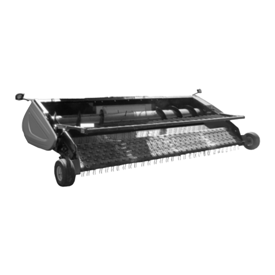
2.3 Component Identification Being able to identify the parts and systems of your pick-up header will make looking up content in its reference manuals much easier. Figure 2.3: PW8 Pick-Up Header A - Transport Light B - Endshield (Fixed) C - Transition Frame... -
Page 37: Definitions
PRODUCT OVERVIEW 2.4 Definitions Understanding the technical terms and acronyms used throughout this document will improve your ability to apply the procedures detailed herein. Term Definition Auto header height control AHHC American Petroleum Institute American Society of Testing and Materials ASTM A headed and externally threaded fastener that is designed to be paired with a nut Bolt... - Page 38 PRODUCT OVERVIEW Term Definition The relationship between the assembly torque applied to a piece of hardware and the Torque-tension axial load it induces in the bolt or screw A thin cylinder with a hole or slot located in the center and is to be used as a spacer, load Washer distribution element or a locking mechanism 215575...
-
Page 39: Chapter 3: Operation
Chapter 3: Operation Safely operating your pick-up header requires familiarizing yourself with its capabilities. 3.1 Owner/Operator Responsibilities Owning and operating heavy equipment comes with certain duties. CAUTION • It is your responsibility to read and understand this manual completely before operating the header. Contact your Dealer if an instruction is not clear to you. -
Page 40: Operational Safety
OPERATION 3.2 Operational Safety Follow all the safety and operational instructions given in this manual and in your combine operator's manual. If you do not have a combine operator’s manual, get one from your Dealer and read it thoroughly. CAUTION •... -
Page 41: Endshields
OPERATION 3.3 Endshields The endshields are molded polyethylene covers attached to the ends of the header. They provide shielding for the header drive components and also display the make of the combine. The left endshield is hinged to the endsheet and can be opened for routine maintenance or easily removed for major servicing. -
Page 42: Closing Left Endshield
OPERATION 3.3.2 Closing Left Endshield Close the endshield when your maintenance or repair tasks are complete. 1. Move endshield (A) slightly so that support (B) can be moved out of the locked position. Figure 3.3: Endshield Support 2. Close endshield (A), ensuring that magnet (B) and stop (C) in the header frame are aligned. -
Page 43: Removing Left Endshield
OPERATION 4. Close endshield (C) and use a slotted screwdriver to turn latch (A) clockwise until it stops (slightly more than one half turn). NOTE: When the latch is fully engaged, the slot will align with notch (B), and the endshield will draw tightly against the header. -
Page 44: Installing Left Endshield
OPERATION 5. Swing endshield (A) fully backward and loosen nuts (B) on clips (C) at the back of the endshield so that the clips disengage from the slots in the header frame. 6. Move endshield (A) away from the header. Figure 3.8: Removing Endshield 3.3.4 Installing Left Endshield Reinstall the endshield when you are done servicing the left side of the header. - Page 45 OPERATION 5. Close endshield (A), ensuring that magnet (B) and stop (C) in the header frame are aligned. Doing so will ensure that latch (D) aligns with receptacle (E). NOTE: The positions of latch (D) and magnet (B) are factory-set and should not require adjustment.
-
Page 46: Removing Right Endshield
OPERATION 10. Close endshield (C) and use a slotted screwdriver to turn latch (A) clockwise until it stops (slightly more than one half turn). NOTE: When the latch is fully engaged, the slot will align with notch (B), and the endshield will draw tightly against the header. - Page 47 OPERATION 3. Position endshield (C) against the header frame, and install nuts and bolts (B) to attach the upper endshield brackets to the header frame. Do NOT tighten the nuts at this time. 4. Install nuts and bolts (A) to attach the lower endshield brackets to frame.
-
Page 48: Header Lift Cylinder Safety Props
OPERATION 3.4 Header Lift Cylinder Safety Props The lift cylinder safety props on your combine provide a mechanical stop to keep the header elevated when the engine is off. Refer to your combine’s operator’s manual for instructions on how to engage the lift cylinder safety props. IMPORTANT: Always engage the combine safety props before working on the header in an elevated position. -
Page 49: Engaging Hold-Down Lift Cylinder Safety Props
OPERATION 3.5 Engaging Hold-Down Lift Cylinder Safety Props The hold-down lift cylinder safety props provide a mechanical stop to keep the hold-down elevated when the engine is off. DANGER To avoid bodily injury or death from unexpected start-up or fall of a raised machine, always stop engine and remove key before leaving the operator’s seat, and always engage safety props before going under the machine for any reason. -
Page 50: Daily Start-Up Check
OPERATION 3.6 Daily Start-Up Check Perform this procedure before starting the combine and pick-up header. CAUTION • Ensure that the combine and header are properly attached and that all controls are in neutral and the combine brake is engaged. • Clear the area of bystanders, pets, etc. Keep children away from the machinery. -
Page 51: Shutting Down The Machine
OPERATION 3.7 Shutting Down the Machine Perform this procedure to safely shut down the combine and pick-up header. DANGER Never start or move the machine until you are sure all bystanders have cleared the area. Before leaving the combine seat for any reason, follow this entire procedure: 1. -
Page 52: Break-In Period
OPERATION 3.8 Break-In Period Follow this procedure during the first 10 hours of operating your pick-up header. DANGER To avoid injury or death from unexpected start-up of the machine, always stop the engine and remove the key from the ignition before leaving the operator’s seat for any reason. 1. -
Page 53: Changing Header Opening
Change the header opening of the pick-up header to configure it to operate with different combine makes and models. To minimize setup at the dealership, PW8 Pick-Up Headers are factory-configured to suit a particular combine make, model, and feeder house size. Each header configuration includes the parts and hardware needed to fit a different combine model within the same brand family. -
Page 54: Header Attachment And Detachment
The process to attach the pick-up header to, and detach it from, a combine depends on the make and model of the machine. This section provides instructions for attaching/detaching the PW8 Pick-Up Header to/from the combines listed in Table 3.2, page Table 3.2 Attaching/Detaching PW8 Header to/from Combine... - Page 55 OPERATION 3. Drive the combine slowly up to the header until the feeder house is directly under top beam (A), and pins (B) are under hooks (C). Figure 3.20: Feeder House 4. Raise the feeder house until transition frame top beam (A) is fully resting on the feeder house.
- Page 56 OPERATION 8. If you are unable to push down the lever, check the alignment of the mounts on both sides of the feeder house. If necessary, loosen nuts (A) and position mount (B) to line up with the pin. Retighten the nuts and ensure that both locking pins are extended into the mounts.
-
Page 57: Detaching From Agco Ideal ™ Combine
OPERATION 13. Lower handle (A) to release multicoupler (B) from the header. 14. Open cover (C) on the combine receptacle. 15. Push handle (D) to the fully open position. 16. Clean the mating surfaces of the multicoupler and the receptacle, if necessary. Figure 3.26: Multicoupler Receptacles 17. - Page 58 OPERATION 3. Lower handle (A) on header receptacle (B). Figure 3.28: Header Receptacle 4. Push combine receptacle handle (B) to the fully open position to release multicoupler (A). Figure 3.29: Combine Receptacle 5. Position multicoupler (B) onto the header receptacle, and move handle (A) to the vertical position to lock the multicoupler.
- Page 59 OPERATION 6. Open the combine output shaft cover. 7. Pull back driveline collar (A) and remove the driveline from combine output shaft (B). Figure 3.31: Detaching Driveline 8. Pull back collar (A) on the end of the driveline and push onto storage bracket (B) until the collar locks.
-
Page 60: Case Ih
OPERATION 11. Start the combine and lower the header to the ground until the feeder house pins (A) are clear of hooks (B). 12. Slowly back the combine away from the header. Figure 3.34: Lowering Feeder House 3.10.2 Case IH This section provides instructions for attaching/detaching the pick-up header to/from Case IH 50/60/7088, 51/61/7130, 51/61/7140, 70/8010, 71/81/9120, 72/82/9230, and 72/82/9240 combines. - Page 61 OPERATION 2. Start the engine. 3. Drive the combine slowly up to the header until feeder house saddle (A) is directly under header top beam (B). 4. Raise the feeder house slightly to lift the header, ensuring that feeder house saddle (A) is properly engaged in the header frame.
- Page 62 OPERATION 10. Rotate disc (B) on header driveline storage hook (A) and remove the driveline from the hook. Figure 3.38: Driveline in Storage Position 11. Pull back collar (A) on the end of the driveline and push it onto combine output shaft (B) until the collar locks. Figure 3.39: Attaching Driveline 12.
-
Page 63: Detaching Header From Case Ih Combine
OPERATION 15. Position coupler (A) onto the header receptacle and push handle (B) downward to engage the coupler pins in the receptacle. 16. Push the handle to the closed position until lock button (C) snaps out. 17. Open cover (D) on the header electrical receptacle. 18. - Page 64 OPERATION 4. Position coupler (A) onto storage plate (B) on the combine. Figure 3.43: Coupler Storage Location 5. Disconnect electrical connector (A) from the header. Figure 3.44: Electrical Connector 6. Place electrical connector (A) into storage cup (B) on the combine.
- Page 65 OPERATION 7. Close the cover on header electrical receptacle (A). 8. Push handle (B) on the header down into the storage position until lock button (C) snaps out. 9. Close cover (D). Figure 3.46: Locking Multicoupler 10. Open driveshield (A) on the combine. 11.
-
Page 66: Challenger®, Gleaner®, And Massey Ferguson
OPERATION 12. Slide the driveline into storage hook (A) on the header and rotate disc (B) to secure the driveline. Figure 3.48: Driveline in Storage Position 13. Close driveshield (A) on the combine. Figure 3.49: Driveshield 14. Lift lever (A) and lower handle (B) to disengage the feeder house/header lock (C). -
Page 67: Attaching Header To Challenger®, Gleaner®, And Massey Ferguson® Combines
OPERATION • Gleaner® R65, 66, 67, 75, 76, 77, and all S and A Series • Massey Ferguson® 9005, and 9500 Series Attaching Header to Challenger®, Gleaner®, and Massey Ferguson® Combines Attach the header to the combine to be able to operate the header using the combine operator’s console. DANGER To avoid injury or death from unexpected start-up of the machine, always stop the engine and remove the key from the ignition before leaving the operator’s seat for any reason. - Page 68 OPERATION 2. Check distance (A) between the underside of top beam (B) and the alignment holes in lower beam (C) on the header. Distance (A) should measure 793–799 mm (31–31 1/2 in.). 3. If necessary, loosen six bolts (D) and adjust lower beam (C) to adjust distance (A) to the correct value.
- Page 69 OPERATION Figure 3.56: Header Opening – Gleaner ® ® R and S Series 6. Raise the feeder house, ensuring that feeder house saddle (A) and the alignment pins are properly engaged in the header frame. 7. Position the header slightly off the ground, stop the engine, and remove the key from the ignition.
- Page 70 OPERATION 8. Insert the hooks into the header by moving lever (A) from the horizontal to the vertical position. Figure 3.59: Engaging Hooks 9. Rotate disc (B) on header driveline storage hook (A), and remove the driveline from the hook. Figure 3.60: Driveline in Storage Position 10.
- Page 71 OPERATION 11. Lower handle (A) to release coupler (B) from the header. Figure 3.62: Coupler 12. Push handle (A) on the combine to the fully open position. 13. Clean the mating surfaces of coupler (B) and receptacle (C), if necessary. Figure 3.63: Opening Receptacle 14.
-
Page 72: Detaching Header From Challenger®, Gleaner®, And Massey Ferguson® Combine
OPERATION Detaching Header from Challenger®, Gleaner®, and Massey Ferguson® Combine Be sure to place the header driveline on its storage bracket when detaching it from a Challenger®, Gleaner®, or Massey Ferguson® combine. WARNING To avoid bodily injury or death from unexpected startup of machine, always stop the engine and remove the key from the ignition before leaving the operator’s seat for any reason. - Page 73 OPERATION 6. Pull back collar (A) on driveline (B), and remove the driveline from the combine. Figure 3.67: Detaching Driveline 7. Slide driveline into storage hook (A) on the header and rotate disc (B) to secure the driveline. Figure 3.68: Driveline in Storage Position 8.
-
Page 74: John Deere 60, 70, S, And T Series
Figure 3.70: Disengaging Header 3.10.4 John Deere 60, 70, S, and T Series This section provides instructions for attaching/detaching the PW8 Pick-Up Header to/from John Deere 96/97/9860STS, 96/97/9870, S650/660/670/680/690, 9660WTS,and T670 combines. Attaching Header to John Deere 60, 70, S, or T Series Combine Attach the header to the combine to be able to operate the header using the combine operator’s console. - Page 75 OPERATION 2. Start the engine. 3. Drive the combine slowly up to the header until feeder house saddles (A) are directly under header top beam (B). 4. Raise the feeder house to lift the header, ensuring that feeder house saddles (A) are properly engaged in the header frame.
- Page 76 OPERATION 8. Pull back collar (A) on the end of the driveline and slide the driveline onto the feeder house driveshaft until the collar locks. 9. Close the feeder house driveshield. Figure 3.75: Attaching Driveline to Combine 10. Remove cover (A) from the combine multicoupler receptacle.
- Page 77 OPERATION 12. Place coupler (A) onto the combine receptacle. 13. Pull out knob (B) to release the handle, and pull handle (C) to engage the pins in coupler. Figure 3.78: Engaging Coupler 14. Pull handle (A) from the vertical to the fully horizontal position to fully engage the multicoupler and to extend pins (B) at the base of the feeder house into locking plates (C).
-
Page 78: Detaching Header From John Deere 60, 70, S, And T Series Combine
OPERATION NOTE: If the handle does not move to the fully horizontal position, verify that locking plates (A) on the header are aligned with locking pins (B) on either side of the feeder house. If necessary, loosen nuts (C) and adjust plates (A) to line up with pins (B). - Page 79 OPERATION 4. Lower handle (A) on the header, and position coupler (B) onto the header as shown. Figure 3.82: Replacing Coupler 5. Raise handle (A) to lock the coupler. 6. Open feeder house driveshield (B). Figure 3.83: Locking Coupler 7. Pull back collar (A) on the driveline, and remove the driveline from the combine output shaft.
-
Page 80: New Holland Cr/Cx Series Combine
11. Slowly back the combine away from the header. Figure 3.86: Disengaging Header 3.10.5 New Holland CR/CX Series Combine This section provides instructions for attaching/detaching the PW8 Pick-Up Header to/from all New Holland CR/CX Series combines. Attaching Header to New Holland CR/CX Series Combine Attach the header to the combine to be able to operate the header using the combine operator’s console. - Page 81 OPERATION 1. Pull handle (A) on the the combine to raise hooks (B) on both sides of the feeder house. Figure 3.87: Feeder House Locks 2. Start the engine. 3. Drive the combine slowly up to the header until feeder house saddle (A) is directly under header top beam (B).
- Page 82 OPERATION 5. Shut down the engine, and remove the key from the ignition. 6. Lift lever (A) on the left side of the header’s feeder house and push handle (B) on the combine so that hooks (C) engage pins (D) on both sides of the feeder house. 7.
- Page 83 OPERATION 11. Pull back collar (B) on the end of the driveline and push it onto combine output shaft (A) until the collar locks. Figure 3.91: Attaching Driveline 12. Open cover (A). 13. Push in lock button (B) and pull handle (C) halfway up to the open position.
-
Page 84: Detaching Header From New Holland Cr/Cx Combine
OPERATION 15. Position the coupler onto header receptacle (A) and push handle (B) downward to engage the pins into the receptacle. 16. Push handle (B) to the closed position until lock button (C) snaps out. 17. Open cover (D) on the header electrical receptacle. 18. - Page 85 OPERATION 5. Position coupler (A) onto storage plate (B) on the combine. 6. Disconnect the electrical connector from the header, and place in storage cup (C) on the combine. Figure 3.96: Coupler and Electrical Connector Storage Location 7. Close cover (A) on the header hydraulic receptacle, and cover (B) on the electrical receptacle.
-
Page 86: Versatile
Figure 3.100: Disengaging Header 3.10.6 Versatile This section provides instructions for attaching/detaching the PW8 Pick-Up Header to/from Versatile RT490 combines. Attaching Header to Versatile Combine Attach the header to the combine to be able to operate the header using the combine operator’s console. - Page 87 OPERATION 1. Check that pins (A) at the lower corners of the header opening are retracted. Figure 3.101: Locking Pins Retracted 2. Start the engine. 3. Drive the combine slowly up to the header until feeder house posts (A) are directly under header top brackets (B). 4.
- Page 88 OPERATION 8. Measure the misalignment between pin (A) and feeder house receptacle (B). 9. Start the engine. 10. Lower the header to the ground until the feeder house disengages from the top beam. 11. Shut down the engine, and remove the key from the ignition.
- Page 89 OPERATION 14. Move support channel (A) according to the measurement made in Step 8, page 72 to align the locking pin with the feeder house receptacle. For instructions, refer to Step page 15. Tighten all the bolts. 16. Start the engine. Figure 3.107: Top Beam —...
- Page 90 OPERATION 20. Pull back collar (A) at the end of the driveline and push it onto combine output shaft (B) until the collar locks. Figure 3.110: Driveline 21. Open cover (A) on the header receptacle. 22. Push in lock button (B) and pull handle (C) upward to the fully open position.
-
Page 91: Detaching Header From Versatile Combine
OPERATION 24. Position coupler (A) onto the header receptacle and push handle (B) downward to engage the coupler pins into the receptacle. 25. Push the handle to the closed position until lock button (C) snaps out. 26. Open cover (D) on the header electrical receptacle. 27. - Page 92 OPERATION 5. Position coupler (A) onto storage plate (B) on the combine. 6. Disconnect the electrical connector from the header, and place in storage cup (C) on the combine. Figure 3.115: Coupler and Electrical Connector Storage Location 7. Close cover (A) on the header hydraulic receptacle, and cover (B) on the electrical receptacle.
- Page 93 OPERATION 10. Slide the driveline into storage hook (A) on the header and rotate disc (B) to secure the driveline. Figure 3.118: Driveline 11. Rotate pin stop (C) from the lowered position as shown in the inset illustration, and disengage pin (B) from the feeder house using handle (A).
-
Page 94: Header Transport
OPERATION 3.11 Header Transport Refer to your combine operator’s manual for instructions on how to transport a header attached to the combine. 3.11.1 Transport Lights Transport lights (A), which are mounted on both ends of the header, are activated by switches inside the combine cab. They function as flashing amber hazard lights and turn signals, and should be positioned perpendicular to the endsheet. -
Page 95: Header Operation
OPERATION 3.12 Header Operation Satisfactory operation of the header in all situations requires making adjustments to the header according to the operating conditions. Proper operation reduces crop loss and increases productivity. Proper adjustments and timely maintenance will increase the service life of your machine. The variables listed in Table 3.3, page 79 and those detailed in this chapter affect header performance. -
Page 96: Adjusting Draper Speed
OPERATION The following operating speed is suggested: Front and Rear Deck Aft Roller: 51 rpm per 1.6 km/h (1 mph) of combine ground speed. Example: For combining at 8 km/h (5 mph), the rear roller shaft should run at 51 x (8/1.6) = 255 rpm (51 x 5 mph = 255 rpm). -
Page 97: Auger Float
OPERATION auger prior to operating the pick-up header to ensure that the auger rotates freely without touching the auger pan or stripper bars. 1. Ensure that clearance (A) between auger flighting (B) and pan (C) is 5–14 mm (3/16–9/16 in.). Figure 3.123: Clearance between Auger and Pan 2. - Page 98 OPERATION 3. Open left endshield (A). For instructions, refer to 3.3.1 Opening Left Endshield, page 4. Remove the right endshield. For instructions, refer to 3.3.5 Removing Right Endshield, page Figure 3.125: Left Endshield 5. Loosen two bolts (A) on auger upstops (B) on the left side of the header.
- Page 99 OPERATION 11. Close left endshield (A). For instructions, refer to 3.3.2 Closing Left Endshield, page 12. Install the right endshield. For instructions, refer to 3.3.6 Installing Right Endshield, page Figure 3.128: Left Endshield Unlocking Auger Float By moving the upstop blocks, the float height of the auger can be set to the desired range. WARNING To avoid bodily injury or death from unexpected startup of machine, always stop the engine and remove the key from the ignition before leaving the operator’s seat for any reason.
- Page 100 OPERATION 5. Loosen two bolts (A) on auger upstops (B) at the left side of header. 6. Slide stops (C) upwards. The height of the stop determines the float range of the auger. 7. Tighten bolts (A). Figure 3.130: Left Stop 8.
-
Page 101: Adjusting Auger Position
OPERATION Adjusting Auger Position The auger is adjustable on both ends in order to maintain uniform clearance across the entire width of the header. WARNING To avoid bodily injury or death from unexpected startup of machine, always stop the engine and remove the key from the ignition before leaving the operator’s seat for any reason. -
Page 102: Stripper Plate Clearance
OPERATION Stripper Plate Clearance The pick-up header is equipped with a pair of stripper plates located on either side of the center opening. The stripper plates are designed to minimize crop carryover behind the auger, but they require proper adjustment. Stripper plates (A) can be found on either side of the header’s center opening. -
Page 103: Adjusting The Stripper Bracket Width - Gleaner® Combines
OPERATION Adjusting Stripper Plate Clearance Adjust the clearance between the stripper plates and the auger flighting so that there is no interference between these parts. DANGER To avoid injury or death from unexpected start-up of the machine, always stop the engine and remove the key from the ignition before leaving the operator’s seat for any reason. - Page 104 OPERATION Figure 3.139: Factory Configuration 816 mm (32-1/8 in.) A - Right Stripper Bracket Bolts x 4 B - Right Side Filler Bolt C - Right Stripper to Center of Feed Pan 729 mm D - Left Stripper Bracket Bolts x 6 E - Left Side Filler Bolts F - Left Stripper to Center of Feed Pan 87 mm Figure 3.140: Narrow Configuration 725 mm (28-1/2 in.)
- Page 105 OPERATION Figure 3.141: Wide Configuration 893 mm (35-1/8 in.) A - Right Stripper Bracket Bolts x 4 B - Right Side Filler Bolt C - Right Stripper to Center of Feed Pan 769 mm D - Left Stripper Bracket Bolts x 6 E - Left Side Filler Bolts F - Left Stripper to Center of Feed Pan 124 mm 3.
-
Page 106: Operating Height
OPERATION 3.12.3 Operating Height The header and pick-up heights can be adjusted to suit various harvest conditions. Adjustments may depend on whether or not your combine is equipped with auto header height control (AHHC). Header Height Header height is the distance between the deck pivot and the ground. Operating height (A) should be set between 4 and 5 on the end plate decal or 305 mm (12 in.) above the ground. -
Page 107: Pick-Up Height
OPERATION Pick-Up Height Pick-up height is the distance between the pick-up fingers and the ground. Pick-up height (A) should be set to 25 mm (1 in.) for most harvest conditions. However: • If the pick-up leaves material in the swath, then the pick-up height is too high and should be decreased. - Page 108 OPERATION 3. Measure pick-up height (A). Refer to Pick-Up Height, page 91, and complete Steps 4, page 92 10, page 92 adjustment is necessary. Figure 3.147: Pick-Up Height 4. Use the combine controls to fully raise the header and take the load off the wheels.
-
Page 109: Adjusting Header Float
OPERATION 3.12.4 Adjusting Header Float The header float setting is factory-configured but can be adjusted for various harvest conditions. WARNING To avoid bodily injury or death from unexpected startup of machine, always stop the engine and remove the key from the ignition before leaving the operator’s seat for any reason. - Page 110 OPERATION 6. Move spring float assembly (A) to float anchor holes (B) to reduce the pressure on the ground wheel, or move spring float assembly to float anchor hole (C) to increase the pressure on the ground wheel. IMPORTANT: To prevent damage to the draper deck, the left and right spring float assemblies must be set to the same anchor hole position.
-
Page 111: Hold-Downs
OPERATION 3.12.5 Hold-Downs Hold-downs help the crop transition smoothly from the drapers to the auger. They can be adjusted to suit various harvest conditions. Hold-Down Position Hold-down position refers to the position of the fiberglass rods on the hold-downs relative to the crop swath and can be adjusted according to harvest conditions. -
Page 112: Adjusting Hold-Down Rod Angle
OPERATION Adjusting Hold-Down Rod Angle The angle between the fiberglass rods and the hold-down support arms is factory-set to optimize crop flow into the combine. The factory setting should be satisfactory for most crop conditions, but the rod angle is adjustable. WARNING To avoid bodily injury or death from unexpected startup of machine, always stop the engine and remove the key from the ignition before leaving the operator’s seat for any reason. -
Page 113: Installing Crop Deflectors
OPERATION 4. On the right side of the header, remove two M12 x 25 bolts and nuts (B). Remove crop deflector (A). 5. Repeat Step 4, page 97 on the left side of the header. 6. Store the deflectors and their hardware in the combine cab or in another safe, dry location. -
Page 114: Driveline
OPERATION 3.12.7 Driveline The driveline connects the header’s chain drive to the combine’s feeder house. Follow these procedures to maximize the life of the driveline. Clutch The header-to-combine driveline contains a radial pin clutch that provides protection against overload. When the auger encounters an obstruction, an overload occurs and the clutch slips while making a rattling sound and pulsating action. - Page 115 OPERATION Driveline guard (A) must always remain attached to the driveline. Tethers (light chains) (B) on either end of the driveline guard prevent the guard from rotating. Remove the guard for maintenance purposes only (refer to Removing Driveline Guard, page 229).
-
Page 116: Unplugging The Header
OPERATION 3.13 Unplugging the Header Be sure to disengage the header drive before attempting to clear a plugged pick-up header. 1. Stop the forward movement of the combine and disengage the header. 2. Fully raise the hold-down. 3. Disengage the pick-up header’s draper drive. IMPORTANT: •... -
Page 117: Adjusting The Pan Seal Assembly
OPERATION 3.14 Adjusting the Pan Seal Assembly The pan seal assembly provides a tighter seal for the rear draper. However, the draper connection hardware will eventually wear down the rubber flap. If plugging occurs between the rear draper and the pan seal bar, the rubber flap can be removed to eliminate the pan seal. -
Page 118: Storing The Header
OPERATION 3.15 Storing the Header Performing these procedures will extend the service life of your pick-up header. CAUTION Never use gasoline, naphtha, or any volatile material for cleaning purposes. These materials may be toxic and/or flammable. 1. Clean the header thoroughly. 2. -
Page 119: Chapter 4: Auto Header Height Control
Chapter 4: Auto Header Height Control Understand the operation of the auto header height control (AHHC) system and how to configure it to work with your combine. 4.1 Auto Header Height Control System Overview The auto header height control (AHHC) feature works in conjunction with the AHHC option available on certain combine models. -
Page 120: Auto Header Height Control Sensor Operation
AUTO HEADER HEIGHT CONTROL 4.2 Auto Header Height Control Sensor Operation The sensors which send height signals to the combine are essentially large resistors which allow a position sensor arm to move and thereby send a position signal to the combine. The position sensors supplied with the auto header height control (AHHC) system are 1000 ohm (1 k) industrial series variable resistors. -
Page 121: Header Height Sensors
AUTO HEADER HEIGHT CONTROL 4.3 Header Height Sensors The header is equipped with two height sensors—one at each end of the header. The height sensors do not require maintenance, but they may need to be repaired or replaced. The sensors may require calibration if there are problems with pick-up height control. Contact your Dealer for more information. -
Page 122: Installing Header Height Sensor Assembly - Left Side
AUTO HEADER HEIGHT CONTROL 4. Disconnect wire harness (A). 5. Push up on rod end clip (B). Slide linkage rod (C) out of rod end clip (B). Figure 4.3: Header Height Sensor Assembly – Left Side 6. Remove nuts and bolts (A). 7. -
Page 123: Removing Header Height Control System - Right Side
AUTO HEADER HEIGHT CONTROL 3. Slide linkage rod (C) into rod end clip (B). Secure the rod end clip by pressing it onto linkage rod (C). 4. Connect wire harness (A). 5. Close the left endshield. Refer to 3.3.2 Closing Left Endshield, page 26 for instructions. - Page 124 AUTO HEADER HEIGHT CONTROL 6. Disconnect wire harness (A). 7. Push up on rod end clip (B). Slide linkage rod (C) out of rod end clip (B). Figure 4.8: Header Height Sensor Assembly – Right Side 8. Remove nuts and bolts (A). 9.
-
Page 125: Installing Header Height Sensor Assembly - Right Side
AUTO HEADER HEIGHT CONTROL 12. Remove long control arm (A) complete with the linkage rod, the rod end clip, and the activator arm. Figure 4.11: Header Height Sensor Assembly – Right Side 4.3.4 Installing Header Height Sensor Assembly — Right Side Be sure to install the right header height sensor with its control arm in a position identical to that of the removed sensor. - Page 126 AUTO HEADER HEIGHT CONTROL 4. Install control arm (C). Ensure that the flat side is facing towards the header. 5. Install sensor (B). Install the bolts in their slots and secure them with nuts (A). Figure 4.14: Header Height Sensor Assembly – Right Side 6.
-
Page 127: Height Sensor Output Voltage Range - Combine Requirements
AUTO HEADER HEIGHT CONTROL 4.4 Height Sensor Output Voltage Range – Combine Requirements The height sensor output must be within a specific voltage range for each combine or the auto header height control (AHHC) feature will not work properly. Table 4.1 Combine Voltage Range Low Voltage Limit High Voltage Limit Minimum Range... - Page 128 AUTO HEADER HEIGHT CONTROL 4. Locate left height sensor (A). NOTE: The sensor and the connector may not be exactly as shown. 5. With the connector plugged into the sensor, measure the voltage between orange signal wire (B) in the middle position on the connector and brown ground wire (C) at one side of the connector.
- Page 129 AUTO HEADER HEIGHT CONTROL 7. Remove two bolts (A) and access panel (B). NOTE: The auger has been removed from the illustration for the sake of clarity. Figure 4.19: Access Panel – Right Side 8. Locate right height sensor (A). NOTE: The sensor may not be exactly as shown.
-
Page 130: Adjusting Header Height Sensor Voltage Range - Left Side
AUTO HEADER HEIGHT CONTROL 4.4.2 Adjusting Header Height Sensor Voltage Range – Left Side If the voltage output range of the left header height sensor does not match the specifications, the sensor’s voltage range must be adjusted. DANGER To avoid injury or death from unexpected start-up of the machine, always stop the engine and remove the key from the ignition before leaving the operator’s seat for any reason. -
Page 131: Note
AUTO HEADER HEIGHT CONTROL 4. Locate access panel (A) on the inside of the right endsheet. Figure 4.22: Access Panel – Right Side 5. Remove two bolts (A) and access panel (B). NOTE: The auger has been removed from the illustration for the sake of clarity. - Page 132 AUTO HEADER HEIGHT CONTROL 9. Install access panel (B) and secure it with bolts (A). NOTE: The auger has been removed from the illustration for the sake of clarity. Figure 4.25: Access Panel – Right Side 215575 Revision B...
-
Page 133: Ideal Series Combines
AGCO Tyton terminal (A) is used to set up and manage a ™ MacDon pick-up header on an IDEAL series combine. Use the touch screen display to select the desired item on the page. - Page 134 AUTO HEADER HEIGHT CONTROL 2. On the COMBINE MAIN MENU, touch HEADER SETTINGS (A). The HEADER SETTINGS page opens. Figure 4.28: Header Settings in Combine Main Menu 215575 Revision B...
- Page 135 3. Touch HEADER CONFIGURATION field (A). A dialog box showing a list of predefined header configuration profiles opens. • If your MacDon header is already set up, it appears on the header list. Touch MacDon header title (B) to highlight the selection in blue, and then touch green check mark (E) to continue.
- Page 136 AUTO HEADER HEIGHT CONTROL 4. To specify the type of header installed on the machine, touch HEADER TYPE field (A). Figure 4.30: Header Settings 5. From the list of predefined header types, touch PICK UP (A). 6. Touch green check mark (B) to save the selection and continue.
- Page 137 AUTO HEADER HEIGHT CONTROL 8. Touch REEL DIAMETER field (A) and a numeric keypad appears. Enter the following value for a MacDon reel: • 11 cm (4.3 in.) 9. Touch REEL PPR (Pulses Per Revolution) field (B) and enter the following as the value for your MacDon header: •...
-
Page 138: Setting Up Automatic Header Controls - Ideal Series
1. Automatic Control Functions: There are toggle (OFF/ON) switches on the HEADER SETTINGS page for the automatic control functions. For MacDon headers, ensure that the following two functions are enabled as shown: • RTC (return to cut) (A) •... -
Page 139: Calibrating The Header - Ideal ™ Series
• Header Lateral Offset: the distance between the centerline of the header and the centerline of the machine. This should be set at 0 for a MacDon header. • Feeder House to Cutter: the distance from the machine interface to the cutterbar. This should be set at 68 for a MacDon header. - Page 140 AUTO HEADER HEIGHT CONTROL 2. Touch HEADER CALIBRATE (A) at the right side of the HEADER SETTINGS CONFIG page. Figure 4.40: Header Settings Page 3. The hazard warning for HEADER CALIBRATION appears. Ensure that all conditions are met. 4. Touch the green check mark at the bottom of the page to start the calibration procedure and follow the on-screen commands.
-
Page 141: Operating The Header - Ideal ™ Series
AUTO HEADER HEIGHT CONTROL 6. When the calibration procedure is complete: • Review summary information (A) • Review green check marks confirming calibrated functions (B) • Touch check mark (C) to save Figure 4.43: Completed Calibration Page NOTE: Touch CALIBRATIONS icon (A) on the MAIN MENU page to display the CALIBRATION MENU where you can choose from a variety of calibrations including header and reel calibration. - Page 142 AUTO HEADER HEIGHT CONTROL The following are used to operate the auto header height control (AHHC) functions: • Tyton terminal (A) • Control handle (B) • Throttle (C) • Header control cluster (D) Refer to the combine operator’s manual to familiarize yourself with the combine’s controls.
-
Page 143: Reviewing Header In-Field Settings - Ideal Series
AUTO HEADER HEIGHT CONTROL 4. Use HEADER HEIGHT SETPOINT control dial (A) as necessary to fine-tune the header position. Figure 4.48: Header Control Cluster 4.5.5 Reviewing Header In-Field Settings – IDEAL ™ ™ Series ™ Once the auto header height control (AHHC) system is working correctly with your IDEAL combine, you can fine-tune these AHHC settings to your liking. - Page 144 AUTO HEADER HEIGHT CONTROL 3. Touching a field opens the on-screen keyboard so that the values can be adjusted. Enter the new value and touch the green check mark. NOTE: Adjustment wheel (A) is located on the right of the Tyton terminal.
-
Page 145: Case Ih 5130/6130/7130 And 5140/6140/7140 Midrange Combines
AUTO HEADER HEIGHT CONTROL 4.6 Case IH 5130/6130/7130 and 5140/6140/7140 Midrange Combines To make your header’s auto header height control (AHHC) system compatible with Case IH 5, 6 and 7 (Midrange) series combines, you must set your combine’s header configuration options for the particular model of header, check the height sensor voltage range, and calibrate the AHHC system to ensure that it is working correctly. -
Page 146: Checking Voltage Range From Combine Cab (Case Ih 5130/6130/7130; 5140/6140/7140)
AUTO HEADER HEIGHT CONTROL 4. Select HEAD 2 tab (A). The HEADER SETUP 2 page appears. 5. From HEADER PRESSURE FLOAT menu (B), select NOT INSTALLED. Figure 4.54: Case IH Combine Display 6. From BELT DRIVE TYPE menu (A), select •... - Page 147 AUTO HEADER HEIGHT CONTROL 2. On the main page of the combine display, select DIAGNOSTICS (A). The DIAGNOSTICS page opens. Figure 4.56: Case IH Combine Display 3. Select SETTINGS (A). The SETTINGS page opens. 4. From GROUP menu (B), select HEADER. Figure 4.57: Case IH Combine Display 5.
-
Page 148: Calibrating Auto Header Height Control (Case Ih 5130/6130/7130; 5140/6140/7140)
AUTO HEADER HEIGHT CONTROL 6. The SETTINGS page updates to display the voltage in VALUE/STATUS field (A). Lower the feeder house fully, and then raise it 305 mm (12 in.) off the ground to view the full range of voltage readings. 7. -
Page 149: Setting Preset Cutting Height (Case Ih 5130/6130/7130; 5140/6140/7140)
AUTO HEADER HEIGHT CONTROL 4.6.4 Setting Preset Cutting Height (Case IH 5130/6130/7130; 5140/6140/7140) Your Case IH 5, 6, or 7 (Midrange) series combine can have up to two auto header height control (AHHC) header height presets configured at one time. NOTE: Changes may have been made to the combine controls or the display since this document was published. - Page 150 AUTO HEADER HEIGHT CONTROL Up and down arrows should now appear in MANUAL HEIGHT box (A) on the RUN 1 page on the combine display. This indicates that the auto header height control (AHHC) is functioning. Figure 4.63: Case Combine Display – Run 1 Page 6.
- Page 151 AUTO HEADER HEIGHT CONTROL 8. If you need to change the position of one of the presets, you can fine-tune this setting with button (A) on the combine console. Figure 4.66: Case Combine Console 215575 Revision B...
-
Page 152: Case Ih 7010/8010, 7120/8120/9120, 7230/8230/9230, And 7240/8240/9240 Combines
AUTO HEADER HEIGHT CONTROL 4.7 Case IH 7010/8010, 7120/8120/9120, 7230/8230/9230, and 7240/8240/9240 Combines To make your header’s auto header height control (AHHC) system compatible with Case IH 7, 8 or 9 series combines, you must set your combine’s header configuration options for the particular model of header, check the height sensor voltage range, and calibrate the AHHC system to ensure that it is working correctly. - Page 153 AUTO HEADER HEIGHT CONTROL 4. Select HDR HEIGHT/TILT (A). The SENSOR page appears. Figure 4.69: Case 8010 Combine Display 5. Select LEFT SEN (A). The exact voltage is displayed. Raise and lower the header to see the full range of voltage readings.
-
Page 154: Checking Voltage Range From Combine Cab (Case Ih 7010/8010; 7120/8120/9120; 7230/8230/9230; 7240/8240/9240)
AUTO HEADER HEIGHT CONTROL 4.7.2 Checking Voltage Range from Combine Cab (Case IH 7010/8010; 7120/8120/9120; 7230/8230/9230; 7240/8240/9240) To ensure that the auto header height control (AHHC) system on your header works correctly with your Case IH 7, 8, or 9 series combine, the output voltage from the header height control sensors must be verified. -
Page 155: Calibrating Auto Header Height Control
AUTO HEADER HEIGHT CONTROL 5. Select HEADER HEIGHT/TILT (A). The PARAMETER page appears. Figure 4.74: Case IH Combine Display 6. Select LEFT HEADER HEIGHT SEN (A) and then select GRAPH button (B). The exact voltage is displayed at the top of the page. - Page 156 AUTO HEADER HEIGHT CONTROL 3. Set the appropriate HEADER STYLE. Figure 4.76: Case IH Combine Display 4. Set the AUTO REEL SPEED SLOPE setting. 5. Set the HEADER PRESSURE FLOAT setting to NO (A) if equipped, and ensure that the REEL DRIVE setting is set to HYDRAULIC (B).
-
Page 157: Calibrating Auto Header Height Control
AUTO HEADER HEIGHT CONTROL 8. Select YES for FORE-AFT CONTROL (A) and HDR FORE-AFT TILT (B) (if applicable). Figure 4.79: Case IH Combine Display 9. Select the HEAD2 tab at the bottom of the page. 10. Ensure that PICKUP (A) is selected from the HEADER TYPE list. - Page 158 AUTO HEADER HEIGHT CONTROL 1. Select TOOLBOX on the MAIN page and then select HEADER SETUP. 2. Locate the HEADER SUB TYPE field. It will be located on either the HEAD 1 or HEAD 2 tab found at the bottom of the display.
-
Page 159: Setting Preset Cutting Height (Case 7010/8010, 7120/8120/9120, 7230/8230/9230, 7240/8240/9240)
AUTO HEADER HEIGHT CONTROL 9. Select CALIBRATION on the combine display and press the right arrow navigation key to enter the information box. 10. Select HEADER (A) and press ENTER. The CALIBRATION dialog box opens. NOTE: You can use the up and down navigation keys to move between the options. - Page 160 AUTO HEADER HEIGHT CONTROL 1. Engage the separator and the header. 2. Manually raise or lower the header to the desired cutting height. 3. Press SET #1 switch (A). HEADER HEIGHT MODE light (C) (next to SET #1 switch) turns on. 4.
-
Page 161: Challenger ® 6 Combines
AUTO HEADER HEIGHT CONTROL ® ® 4.8 Challenger 6 Combines ® To make your header’s auto header height control (AHHC) system compatible with Challenger 6 series combines, you must set your combine’s header configuration options for the particular model of header, check the height sensor voltage range, and calibrate the AHHC system to ensure that it is working correctly. -
Page 162: Engaging Auto Header Height Control - Challenger ® 6 Series
AUTO HEADER HEIGHT CONTROL 5. Fully lower the combine feeder house. NOTE: You may need to hold the HEADER DOWN switch for a few seconds to ensure that the feeder house is fully lowered. 6. Record the height sensor voltage. 7. -
Page 163: Calibrating Auto Header Height Control - Challenger ® 6 Series
AUTO HEADER HEIGHT CONTROL 4.8.3 Calibrating Auto Header Height Control – Challenger ® ® 6 Series ® The auto header height control (AHHC) sensor output must be calibrated for Challenger 6 Series combines, or the AHHC feature will not work properly. NOTE: Changes may have been made to the combine controls or the display since this document was published. - Page 164 AUTO HEADER HEIGHT CONTROL 3. Select HEADER button (A). The HEADER CALIBRATION page displays a warning. ® ® Figure 4.94: Challenger Combine Display 4. Read the warning message, and then press green check mark button (A). ® ® Figure 4.95: Challenger Combine Display 5.
-
Page 165: Adjusting Header Height - Challenger ® 6 Series
AUTO HEADER HEIGHT CONTROL 4.8.4 Adjusting Header Height – Challenger ® ® 6 Series Once the auto header height control (AHHC) system is activated, press and release the HEADER LOWER button on the control handle. The AHHC will automatically lower the header to the preset height. NOTE: Changes may have been made to the combine controls or the display since this document was published. - Page 166 AUTO HEADER HEIGHT CONTROL 2. Press HEADER CONTROL (A). The HEADER CONTROL page appears. ® ® Figure 4.99: Challenger Combine Display 3. Go to the TABLE SETTINGS tab. 4. Press up arrow (A) on MAX UP PWM to increase the percentage number and thereby increase the speed at which the header rises;...
-
Page 167: Setting Sensitivity Of Auto Header Height Control - Challenger ® 6 Series
AUTO HEADER HEIGHT CONTROL 4.8.6 Setting Sensitivity of Auto Header Height Control – Challenger ® ® 6 Series The sensitivity adjustment controls the distance the header must travel up or down before the auto header height control (AHHC) reacts and raises or lowers the feeder house. When the sensitivity is set to maximum, only small changes in ground height are needed to cause the feeder house to rise or fall. -
Page 168: Gleaner R65/R66/R75/R76 And S Series Combines - Except S9 Series
AUTO HEADER HEIGHT CONTROL R65/R66/R75/R76 and S Series Combines – Except S9 Series ® ® 4.9 Gleaner ® To make your header’s auto header height control (AHHC) system compatible with Gleaner R65/R66/R75/R76 and non-S9 S series combines, you must set your combine’s header configuration options for the particular model of header, check the height sensor voltage range, adjust the header height response rate and ground pressure settings, and calibrate the AHHC system to ensure that it is working correctly. -
Page 169: Engaging Auto Header Height Control - Gleaner ® R65/R66/R75/R76 And S Series
AUTO HEADER HEIGHT CONTROL 4.4 Height Sensor Output Voltage Range – Combine 5. If the sensor voltage is not within the low and high limits shown in Requirements, page 111, or if the range between the low and high limits is insufficient, adjustments to the height 4.4.2 Adjusting Header Height Sensor Voltage Range –... -
Page 170: Calibrating Auto Header Height Control - Gleaner ® R65/R66/R75/R76 And S Series
NOT be in auto or standby mode. The engine rpm must be above 2000 rpm. The header tilt option on 2004 and earlier model combines does NOT work with MacDon headers. This system will have to be removed and disabled in order to calibrate the AHHC system. - Page 171 AUTO HEADER HEIGHT CONTROL Figure 4.107: Combine Auto Header Height Controls A - AUTO MODE Button B - AHHC Light C - CAL1 Button D - Raise Header E - Lower Header F - Auto Mode G - CAL2 Button 1.
-
Page 172: Turning Accumulator Off - Gleaner ® R65/R66/R75/R76 And S Series
AUTO HEADER HEIGHT CONTROL 4.9.4 Turning Accumulator Off – Gleaner ® ® R65/R66/R75/R76 and S Series ® Activating the accumulator on a Gleaner R65/R66/R75/R76 and non-S9 S series combine will negatively affect the speed at which the AHHC system adjusts the height of the header. Turning the accumulator off will ensure good AHHC performance. -
Page 173: Adjusting Ground Pressure - Gleaner R65/R66/R75/R76 And S Series
AUTO HEADER HEIGHT CONTROL The auto header height control (AHHC) system’s stability is affected by the rate at which the hydraulic fluid flows through the hydraulic system. Ensure that header raise (A) and header lower (B) adjustable restrictors in the hydraulic valve block are adjusted so that it takes approximately 6 seconds to raise the header from ground level to its maximum height (with the hydraulic cylinders fully extended), and approximately... -
Page 174: Adjusting Sensitivity Of Auto Header Height Control - Gleaner R65/R66/R75/ R76 And S Series
AUTO HEADER HEIGHT CONTROL 4.9.7 Adjusting Sensitivity of Auto Header Height Control – Gleaner ® ® R65/R66/R75/ R76 and S Series ® Setting the sensitivity of the auto header height control (AHHC) system on a Gleaner R65/R66/R75/R76 and non-S9 S Series combine affects how quickly the AHHC system changes the height of the header. NOTE: ®... -
Page 175: Troubleshooting Alarms And Diagnostic Faults - Gleaner ® R65/R66/R75/R76 And S Series
AUTO HEADER HEIGHT CONTROL 4.9.8 Troubleshooting Alarms and Diagnostic Faults – Gleaner ® ® R65/R66/R75/R76 and S Series ® Errors in the auto header height control (AHHC) system on Gleaner R65/R66/R75/R76 and non-S9 S series combines appear on a display on the combine’s Electronic Instrument Panel (EIP). NOTE: ®... - Page 176 AUTO HEADER HEIGHT CONTROL Alarm conditions: If an error message is received from the fuse panel, an audible alarm sounds. The LCD on the electronic instrument panel (EIP) indicates a header system error as HDR CTRL followed by HGT ERR for height, and HDR CTRL followed by TILT ERR for tilt.
-
Page 177: Gleaner S9 Series Combines
The AGCO Tyton terminal is used to set up and manage a ® MacDon header on a Gleaner S9 combine. The terminal has a touch screen. Touch the terminal screen to select an item. - Page 178 AUTO HEADER HEIGHT CONTROL 2. On the COMBINE MAIN MENU, touch HEADER SETTINGS (A). The HEADER SETTINGS page appears. Figure 4.116: Header Settings in Combine Main Menu 215575 Revision B...
- Page 179 3. Touch HEADER CONFIGURATION field (A). A page showing the predefined header profiles opens. • If your MacDon header is already set up, it appears on header list. Touch MacDon header title (B) to highlight the selection in blue, and then touch green check mark (E) to continue.
- Page 180 AUTO HEADER HEIGHT CONTROL 4. To specify the type of header installed on the combine, touch HEADER TYPE field (A). Figure 4.118: Header Settings 5. A list of predefined header types appears. • For a pick-up header, select PICK UP (A). •...
-
Page 181: Setting Up Automatic Header Controls - Gleaner ® S9 Series
Enter 40 for the MacDon reel diameter. 8. Touch REEL PPR (speed pulses per revolution) field (B) and enter 30 as the PPR value for your MacDon header. NOTE: PPR is the number of teeth on the reel speed sprocket. - Page 182 AUTO HEADER HEIGHT CONTROL 1. Automatic Control Functions: There are toggle (OFF/ON) switches on the HEADER SETTINGS page for automatic height control functions. For MacDon headers, ensure that the following functions are enabled: • RTC (return to cut) (A) • AHHC (automatic header height control) (B) All other switches should be disabled (i.e.
-
Page 183: Calibrating Header - Gleaner S9 Series
• Header Lateral Offset: this is the distance between the centerline of the header and the centerline of the machine. This should be set at 0 for a MacDon header. • Feeder House to Cutter: this is the distance from the machine interface to the cutterbar. - Page 184 • Left and right header sensor outputs (V) (the values should be identical with MacDon headers) • Header height sensor (mA) • Tilt position sensor (mA) The modes applicable to MacDon headers are shown with check marks below line (C): • Return to cut • Automatic header height control Figure 4.130: Header Calibration Page...
- Page 185 AUTO HEADER HEIGHT CONTROL 3. On the ground speed lever (GSL), press HEADER DOWN button (A). The sensor values on the HEADER CALIBRATION page will change as the header falls. NOTE: The header needs to be fully lowered and then fully raised. The sensor voltage range should be between 0.7 and 4.3 V.
- Page 186 AUTO HEADER HEIGHT CONTROL A progress bar will appear. The calibration wizard can be stopped at any time by touching the red X. The header moves automatically during this process. Figure 4.134: Calibration In Progress 7. When the calibration procedure is complete, a message appears displaying summary information (A).
-
Page 187: Operating With A Gleaner ® S9 Series Combine
AUTO HEADER HEIGHT CONTROL ® ® 4.10.4 Operating with a Gleaner S9 Series Combine ® Once the auto header height control (AHHC) system has been configured on your Gleaner S9 series combine, the AHHC system can be controlled from the combine cab. NOTE: Changes may have been made to the combine controls or the display since this document was published. -
Page 188: Header In-Field Settings For Gleaner ® S9 Series Combine
AUTO HEADER HEIGHT CONTROL 4. Press AHHC control switch (A) on the ground speed lever (GSL) to engage the AHHC. The header positions itself to the last-saved setpoint position. Figure 4.139: AHHC on GSL 5. Use HEADER HEIGHT SETPOINT control dial (A) as necessary to fine-tune the setpoint position. - Page 189 AUTO HEADER HEIGHT CONTROL 1. To view the header group settings, touch HEADER icon (A). 2. The display area shows: • Left header height indicator (B), which shows the current position of the header. • Red line (C) on current header height position indicator (B), which shows the setpoint cut-off position.
- Page 190 AUTO HEADER HEIGHT CONTROL NOTE: Header height setpoint control dial (A) is on the header control cluster. Figure 4.143: Header Control Cluster 215575 Revision B...
-
Page 191: John Deere 60 Series Combines
AUTO HEADER HEIGHT CONTROL 4.11 John Deere 60 Series Combines To make your header’s auto header height control (AHHC) system compatible with John Deere 60 series combines, you must check the height sensor voltage range, adjust the header height response rate and drop settings, and calibrate the AHHC system to ensure that it is working correctly. -
Page 192: Calibrating Auto Header Height Control (John Deere 60 Series)
AUTO HEADER HEIGHT CONTROL 6. Start the combine and lower the feeder house to the ground. Keep doing this until the feeder house stops moving. NOTE: You may need to hold the HEADER DOWN switch for a few seconds to ensure that the feeder house is fully lowered. 7. -
Page 193: Turning Off Accumulator (John Deere 60 Series)
AUTO HEADER HEIGHT CONTROL 4. Press the UP or DOWN buttons until HDR appears on the monitor. 5. Press the ENTER button. HDR H-DN appears on the monitor. 6. Fully lower the feeder house to the ground. NOTE: You may need to hold the HEADER DOWN switch for a few seconds to ensure that the feeder house is fully lowered. -
Page 194: Setting Sensing Grain Header Height (John Deere 60 Series)
AUTO HEADER HEIGHT CONTROL 1. Press DIAGNOSTIC button (A) on monitor. DIA appears on the monitor. 2. Press UP button (B) until EO1 appears on the monitor, and press ENTER (D). This is the header adjustment setting. 3. Press UP (B) or DOWN (C) button until 132 is displayed on the top portion of the monitor. -
Page 195: Setting Sensitivity Of Auto Header Height Control (John Deere 60 Series)
AUTO HEADER HEIGHT CONTROL NOTE: Do NOT use active header float function (A) in combination with the AHHC system; the two systems will counteract each other. Header symbol (B) on the display should NOT have a wavy line under it and should appear exactly as shown on the Active Header Control Display in Figure 4.150, page... -
Page 196: Adjusting Threshold For Drop Rate Valve (John Deere 60 Series)
AUTO HEADER HEIGHT CONTROL 4.11.6 Adjusting Threshold for Drop Rate Valve (John Deere 60 Series) The speed at which the header rises or falls on a John Deere 60 series combine can be adjusted from the combine cab. NOTE: Changes may have been made to the combine controls or the display since this document was published. Refer to the combine operator’s manual for updated information. -
Page 197: John Deere 70 Series Combines
AUTO HEADER HEIGHT CONTROL 4.12 John Deere 70 Series Combines To make your header’s auto header height control (AHHC) system compatible with John Deere 70 series combines, you must check the height sensor voltage range, calibrate the feeder house speed, calibrate the AHHC system to ensure that it is working correctly, and adjust the header sensitivity. - Page 198 AUTO HEADER HEIGHT CONTROL 4. Use scroll knob (A) to highlight the middle icon (the green i) and press check mark button (B) to select it. The Message Center will appear. Figure 4.156: John Deere Combine Control Console 5. Use the scroll knob to highlight DIAGNOSTIC ADDRESSES (A) from the right column.
-
Page 199: Calibrating Feeder House Speed (John Deere 70 Series)
AUTO HEADER HEIGHT CONTROL 8. Use scroll knob to highlight down arrow (A) and press the check mark button to scroll through the list until 029 DATA (B) is displayed and voltage reading (C) appears on the combine display. 9. Start the combine and fully lower the feeder house to the ground. - Page 200 AUTO HEADER HEIGHT CONTROL 2. Press the button located fourth from the left along the top of monitor (A) to select the icon (B) resembling an open book with a wrench on it. 3. Press button (A) a second time to enter the diagnostics and calibration mode.
-
Page 201: Setting Sensitivity Of Auto Header Height Control (John Deere 70 Series)
AUTO HEADER HEIGHT CONTROL 4.12.4 Setting Sensitivity of Auto Header Height Control (John Deere 70 Series) Setting the sensitivity (sometimes called “dead-band adjustment”) of the auto header height control (AHHC) system on a John Deere 70 series combine affects how quickly the AHHC system changes the height of the header. NOTE: Changes may have been made to the combine controls or the display since this document was published. - Page 202 AUTO HEADER HEIGHT CONTROL 1. Press button (A). The current raise/lower rate setting will appear on the monitor. NOTE: Lower readings indicate a lower rate of header rise and fall; higher readings indicate a higher rate. 2. Use scroll knob (B) to adjust the rate. The adjustment will be saved automatically.
-
Page 203: John Deere S And T Series Combines
AUTO HEADER HEIGHT CONTROL 4.13 John Deere S and T Series Combines To make your header’s auto header height control (AHHC) system compatible with John Deere S and T series combines, you must check the height sensor voltage range, calibrate the feeder house speed, calibrate the AHHC system to ensure that it is working correctly, and adjust the sensitivity and cutting height presets. - Page 204 AUTO HEADER HEIGHT CONTROL 4. Select AHHC RESUME (A). A list of calibration options appears. Figure 4.169: John Deere Combine Display 5. Select the AHHC SENSING option. 6. Press icon (A) resembling an arrow in a box. The AHHC SENSING menu appears and five pages of information are displayed.
-
Page 205: Calibrating Feeder House Fore-Aft Tilt Range (John Deere S And T Series)
AUTO HEADER HEIGHT CONTROL 4.4 Height Sensor Output Voltage Range – Combine 10. If the sensor voltage is not within the low and high limits shown in Requirements, page 111, or if the range between the low and high limits is insufficient, the height sensors will need to 4.4.2 Adjusting Header Height Sensor Voltage Range –... - Page 206 AUTO HEADER HEIGHT CONTROL 1. Press DIAGNOSTIC icon (A) on the main page of the combine display. The CALIBRATION page appears. Figure 4.174: John Deere Combine Display 2. Select CALIBRATIONS drop-down menu (A) to view the list of calibration options. Figure 4.175: John Deere Combine Display 3.
-
Page 207: Calibrating Auto Header Height Control (John Deere S And T Series)
AUTO HEADER HEIGHT CONTROL 4. Press ENTER icon (A). Figure 4.177: John Deere Combine Display 5. Follow the instructions that appear on the combine display. NOTE: If an error code appears during calibration, the output from the height sensors is out of the specified voltage range and will require adjustment. - Page 208 AUTO HEADER HEIGHT CONTROL 1. Press DIAGNOSTIC icon (A) on the main page of monitor. The CALIBRATION page appears. Figure 4.179: John Deere Combine Display 2. Select THRESHING CLEARANCE (A). A list of calibration options appears. Figure 4.180: John Deere Combine Display 3.
-
Page 209: Setting Sensitivity Of Auto Header Height Control (John Deere S And T Series)
AUTO HEADER HEIGHT CONTROL 5. Press icon (A) with either FEEDER HOUSE SPEED or HEADER selected. The icon will turn green. NOTE: The feeder house speed calibration procedure must be done before the header calibration procedure. Figure 4.182: John Deere Combine Display 6. -
Page 210: Adjusting Manual Header Raise/Lower Rate (John Deere S And T Series)
AUTO HEADER HEIGHT CONTROL 1. Press button (A) twice. The current sensitivity setting will appear on the combine display. Figure 4.184: John Deere Combine Command Center 2. Press – or + icon (A) to adjust the sensitivity. NOTE: The numbers depicted on the displays in these illustrations are for reference purposes only;... -
Page 211: Setting Preset Cutting Height (John Deere S And T Series)
AUTO HEADER HEIGHT CONTROL 1. Press button (A). The current manual raise/lower speed setting will appear on the monitor. Figure 4.186: John Deere Combine Command Center 2. Press – or + icon (A) to adjust the manual raise/lower speed. NOTE: The numbers depicted on the displays in these illustrations are for reference purposes only;... - Page 212 AUTO HEADER HEIGHT CONTROL 1. Press COMBINE – HEADER SETUP icon (A) on the main page. The COMBINE – HEADER SETUP page appears. This page is used to set various header settings such as the reel speed, header width, and the height of the feeder house for acre counter engagement.
- Page 213 AUTO HEADER HEIGHT CONTROL 4. Turn on header engagement switch (A) and move the header to the desired preset position. 5. The header position can be fine-tuned with HEADER HEIGHT PRESSURE CONTROL DIAL (B). Figure 4.191: Combine Control Console 6. Hold joystick button 2 (B) until the AHHC icon flashes on the monitor.
-
Page 214: New Holland Combines Cx/Cr Series (Cr Series - Model Year 2014 And Earlier)
AUTO HEADER HEIGHT CONTROL 4.14 New Holland Combines CX/CR Series (CR Series – Model Year 2014 and Earlier) To make your header’s auto header height control (AHHC) system compatible with New Holland CX and CR series combines (CR models of model year 2014 and earlier), you must check the height sensor voltage range, engage and calibrate the AHHC system, and adjust the sensitivity, header rise and fall rates, and the cutting height presets. - Page 215 AUTO HEADER HEIGHT CONTROL 4. Select GROUP drop-down arrow (A). The GROUP dialog box appears. Figure 4.195: New Holland Combine Display 5. Select HEADER HEIGHT/TILT (A). The PARAMETER page appears. Figure 4.196: New Holland Combine Display 6. Select LEFT HEADER HEIGHT SEN (A), and then select GRAPH button (B).
-
Page 216: Engaging Auto Header Height Control (New Holland Cr/Cx Series)
AUTO HEADER HEIGHT CONTROL 4.14.2 Engaging Auto Header Height Control (New Holland CR/CX Series) Set these initial configuration options on your New Holland CR or CX Series combine when setting up the auto header height control (AHHC) system. NOTE: Changes may have been made to the combine controls or the display since this document was published. For instructions, refer to the combine operator’s manual for updated information. - Page 217 AUTO HEADER HEIGHT CONTROL • The combine is on level ground, with the header level with the ground. • The engine is running. • The combine is not moving. • No faults have been received from the Header Height Controller (HHC) module. •...
-
Page 218: Calibrating Maximum Stubble Height
AUTO HEADER HEIGHT CONTROL Calibrating Maximum Stubble Height The height at which the combine’s harvested area counter stops or starts counting may need to be calibrated for the auto header height control (AHHC) system to work correctly. Set the maximum stubble height to a value that will never be reached while cutting. The area counter will stop counting harvested area when the header is above the programmed height, and will begin counting when the header is below the programmed height. -
Page 219: Adjusting Header Raise Rate (New Holland Cr/Cx Series)
AUTO HEADER HEIGHT CONTROL 4.14.4 Adjusting Header Raise Rate (New Holland CR/CX Series) The speed at which the header rises on a New Holland CR or CX series combine can be adjusted from the combine cab. NOTE: Changes may have been made to the combine controls or the display since this document was published. Refer to the combine operator’s manual for updated information. -
Page 220: Setting Auto Header Height Control Sensitivity To 200 (New Holland Cr/Cx Series)
AUTO HEADER HEIGHT CONTROL 4.14.6 Setting Auto Header Height Control Sensitivity to 200 (New Holland CR/CX Series) Setting the sensitivity of the auto header height control (AHHC) system on a New Holland CR or CX series combine affects how quickly the AHHC system changes the height of the header. The recommended value for these combines is 200. NOTE: Changes may have been made to the combine controls or the display since this document was published. - Page 221 AUTO HEADER HEIGHT CONTROL 5. To change one of the saved header height set points while the combine is in use, use HEADER HEIGHT AND HEADER LATERAL FLOAT rocker switch (A) (slow up/down) to raise or lower the header to the desired height. Press AUTOMATIC HEADER HEIGHT CONTROL button (B) for a minimum of 2 seconds to store the new height position.
-
Page 222: New Holland Combines (Cr Series - Model Year 2015 And Later)
AUTO HEADER HEIGHT CONTROL 4.15 New Holland Combines (CR Series – Model Year 2015 and Later) To make your header’s auto header height control (AHHC) system compatible with New Holland CR series combines of model year 2015 and later (6.80, 6.90, 7.90, 8.90, 9.90, and 10.90), you must check the height sensor voltage range, engage and calibrate the AHHC system, and adjust the sensitivity, cutting height presets and tilt functions. - Page 223 2. Select HEAD 1 (A). The HEADER SETUP 1 page appears. The HEADER TYPE field will automatically register as PICKUP (B). NOTE: HEADER SUB TYPE menu (C) is not applicable to MacDon pickup headers. The menu’s two selectable options – NO HYDR CONTROL and SPARE – have no effect on header performance.
-
Page 224: Checking Voltage Range From Combine Cab (New Holland Cr Series)
AUTO HEADER HEIGHT CONTROL 7. Set the values for HHC HEIGHT SENSITIVITY (A) and HHC TILT SENSITIVITY (B) according to harvest conditions. Figure 4.214: New Holland Combine Display 4.15.2 Checking Voltage Range from Combine Cab (New Holland CR Series) To ensure that the auto header height control (AHHC) system on your header works correctly with your New Holland CR series combine (model year 2015 or later), the output voltage from the header height control sensors must be verified. - Page 225 AUTO HEADER HEIGHT CONTROL 3. Select SETTINGS (A). The SETTINGS page appears. Figure 4.216: New Holland Combine Display 4. Select HEADER HEIGHT/TILT (A) from the GROUP drop- down menu. 5. Select HEADER HEIGHT SENS. L (B) from the PARAMETER drop-down menu. Figure 4.217: New Holland Combine Display 6.
-
Page 226: Calibrating Auto Header Height Control (New Holland Cr Series)
AUTO HEADER HEIGHT CONTROL 4.15.3 Calibrating Auto Header Height Control (New Holland CR Series) The auto header height control (AHHC) sensor output must be calibrated for New Holland CR series combines (model year 2015 and later), or the AHHC feature will not work properly. NOTE: Changes may have been made to the combine controls or the display since this document was published. - Page 227 AUTO HEADER HEIGHT CONTROL 2. Select CALIBRATION drop-down arrow (A). Figure 4.220: New Holland Combine Display 3. Select HEADER (A) from the list of calibration options. Figure 4.221: New Holland Combine Display 4. Follow the calibration steps in the order in which they appear on screen.
-
Page 228: Setting Auto Height (New Holland Cr Series)
The console has two buttons used for auto height presets. The toggle switch used on previous models for auto height presets is now configured as shown at right. MacDon headers require only buttons (A) and (B). Button (C) does not need to be configured. -
Page 229: Setting Maximum Work Height (New Holland Cr Series)
AUTO HEADER HEIGHT CONTROL 3. Select the RUN tab that shows MANUAL HEIGHT. NOTE: The MANUAL HEIGHT field may appear on any of the RUN tabs. When an auto height set point button is pressed, the display will change to AUTO HEIGHT (A) as shown. 4. - Page 230 AUTO HEADER HEIGHT CONTROL 4. Set MAXIMUM WORK HEIGHT to the desired value. 5. Press SET and then press ENTER. Figure 4.229: New Holland Combine Display 215575 Revision B...
-
Page 231: Chapter 5: Maintenance And Servicing
Chapter 5: Maintenance and Servicing The following instructions provide information about routine maintenance and servicing of your pick-up header. For detailed maintenance and service information, contact your Dealer. A parts catalog is provided with your header for ordering replacement parts. Log the hours of operation and use the Maintenance Schedule/Record provided to keep a record of scheduled maintenance. -
Page 232: Maintenance Requirements
MAINTENANCE AND SERVICING 5.2 Maintenance Requirements The maintenance program is organized according to the pick-up header’s operating hours. This system depends on keeping accurate operating logs. Periodic maintenance requirements are organized according to service intervals. Regular maintenance is the best insurance against early wear and untimely breakdowns. Following the maintenance schedule will increase the service life of your machine. - Page 233 MAINTENANCE AND SERVICING Table 5.1 Maintenance Schedule/Record ▲ - Change ü - Check S - Lubricate ACTION: ! Hour meter reading ! Service date ! Serviced by 10 Hours Lubricate auger drive chain – refer to 5.3.3 Lubricating Auger Drive Chain, page 223.
-
Page 234: Preseason/Annual Service
MAINTENANCE AND SERVICING Table 5.1 Maintenance Schedule/Record (continued) ▲ - Change S - Lubricate ü - Check ACTION: 100 Hours Clean and grease driveshaft splines – refer to Cleaning Driveline Splined Shaft, page 233. Lubricate driveline slip-joint and clutch – refer to Lubrication, page 220. -
Page 235: End-Of-Season Service
MAINTENANCE AND SERVICING 5.2.3 End-of-Season Service Perform these procedures when storing the pick-up header at the end of the harvest season. Refer to 3.15 Storing the Header, page 102 for end of season servicing information. 215575 Revision B... -
Page 236: Lubrication
MAINTENANCE AND SERVICING 5.3 Lubrication Proper lubrication is essential to ensuring the service life of the pick-up header. DANGER To avoid personal injury, before servicing the header or opening the drive covers, perform the following procedures: • Lower the header fully. If you intend to work on the header in the raised position, always engage the header lift cylinder safety props on the combine. -
Page 237: Greasing Points
MAINTENANCE AND SERVICING 5.3.2 Greasing Points Add grease to these greasing points according to the maintenance schedule. Be sure to leave a small blob of grease on top of each fitting to prevent contamination. Every 25 Hours • (A) Front draper deck idler bearing (underneath wheel support plate) •... - Page 238 MAINTENANCE AND SERVICING Every 100 Hours Figure 5.4: Greasing Points A - Driveline Slip-Joint B - Driveline Guard (Both Ends) C - Driveline Clutch D - Optional Caster Wheel (Two Places) NOTE: The header illustration shows the factory-equipped fixed wheels. Caster wheels (D) are available as an optional kit, and should be greased if equipped.
-
Page 239: Lubricating Auger Drive Chain
MAINTENANCE AND SERVICING 5.3.3 Lubricating Auger Drive Chain The auger drive chain should be lubricated frequently with SAE 30 engine oil for maximum service life. DANGER To avoid injury or death from unexpected start-up of the machine, always stop the engine and remove the key from the ignition before leaving the operator’s seat for any reason. -
Page 240: Installing Sealed Bearing
MAINTENANCE AND SERVICING 5.4 Installing Sealed Bearing This is a general procedure for installing non-serviceable bearings on the pick-up header. 1. Clean the shaft and apply a rust preventive coating. 2. Install flangette (A), bearing (B), second flangette (C), and lock collar (D). -
Page 241: Drives
MAINTENANCE AND SERVICING 5.5 Drives This section covers maintenance procedures for the header, draper, and auger drives. Consult the maintenance schedule for specific maintenance intervals. 5.5.1 Header Driveshaft Perform this procedure regularly to extend the service life of the driveshaft. Ensure that the splines are free from dust and dirt. -
Page 242: Installing Header Driveline
MAINTENANCE AND SERVICING 3. Disconnect tethers (A) securing the driveline guard to the header. 4. Pull back guard (B) to expose collar (C) at the combine end of the driveline. CAUTION To prevent injury, or damage to the driveline, hold the driveline so that it doesn’t fall to the ground. - Page 243 MAINTENANCE AND SERVICING 2. Pull back guard (A) to expose collar (B) at the header (notched) end of the driveline. NOTE: The driveline may separate if it is not supported at both ends. 3. Pull back collar (B). Slide the coupler onto splined input shaft (C) until it locks.
-
Page 244: Replacing Driveline Clutch
Repair or replace the driveline clutch if it can no longer generate the necessary torque to drive the header. Refer to your PW8 Pick-Up Header Parts Catalog for replacement part numbers. 1. Remove the driveline from the header. For instructions, refer to Removing Header Driveline, page 225. -
Page 245: Removing Driveline Guard
MAINTENANCE AND SERVICING Removing Driveline Guard The driveline guard must remain attached to the driveline during pick-up header operation, but can be removed for maintenance purposes. WARNING To avoid bodily injury or death from unexpected startup of machine, always stop the engine and remove the key from the ignition before leaving the operator’s seat for any reason. - Page 246 MAINTENANCE AND SERVICING 5. Lift the combine end of driveline (A) from the hook, and extend the driveline until it separates. Hold the header end of driveline (B) to prevent it from striking the ground. Figure 5.18: Separated Driveline 6. Use a slotted screwdriver to release grease fitting/lock (A). Figure 5.19: Driveline Guard 215575 Revision B...
-
Page 247: Installing Driveline Guard
MAINTENANCE AND SERVICING 7. Rotate driveline guard locking ring (A) counterclockwise using a slotted screwdriver until lugs (B) line up with the slots in the guard. 8. Pull the driveline guard off the driveline. Figure 5.20: Driveline Guard Installing Driveline Guard The driveline guard protects the pick-up header’s driveline ends from dust and dirt. - Page 248 MAINTENANCE AND SERVICING 2. Push the driveline guard onto the ring until the locking ring is visible in slots (A). Figure 5.22: Driveline Guard 3. Use a slotted screwdriver to rotate ring (A) clockwise to lock the ring in the guard. Figure 5.23: Driveline Guard 4.
-
Page 249: Cleaning Driveline Splined Shaft
MAINTENANCE AND SERVICING 5. Reassemble the driveline. NOTE: The splines are keyed to ensure the proper alignment of the universal joints. Align weld (A) with missing spline (B) when reassembling the driveline. NOTE: If a spline weld is missing, the driveshaft should be replaced. - Page 250 MAINTENANCE AND SERVICING 1. Lower the header to the ground. 2. Shut down the combine and remove the key from the ignition. 3. Disconnect hydraulic hoses (A) from the front motor on the left side of the header. Install caps onto the hose ends, or wrap the hose ends with plastic and move the hoses away from the work area.
-
Page 251: Installing Front Hydraulic Motor
MAINTENANCE AND SERVICING Installing Front Hydraulic Motor The front hydraulic motor is meant to move slightly during operation. Be sure not to overtighten the nuts securing the motor to the header. 1. Apply grease to the splines of the shaft of front hydraulic motor (A). -
Page 252: Removing Rear Hydraulic Motor
MAINTENANCE AND SERVICING 5. Reconnect hydraulic hoses (A) to the motor. Figure 5.32: Hydraulic Hoses Removing Rear Hydraulic Motor Ensure that the connections to the rear hydraulic motor are kept completely clean while the motor is removed. WARNING To avoid bodily injury or death from unexpected startup of machine, always stop the engine and remove the key from the ignition before leaving the operator’s seat for any reason. -
Page 253: Installing Rear Hydraulic Motor
MAINTENANCE AND SERVICING 4. Disconnect hydraulic hoses (A) from the motor. Install plugs onto the hose ends, or wrap the ends with plastic and move the hoses away from the work area. Loosen or remove the cinch straps on the hoses if necessary. IMPORTANT: Keep hydraulic coupler tips and connectors clean. -
Page 254: Removing Hydraulic Motor Hoses
MAINTENANCE AND SERVICING Removing Hydraulic Motor Hoses Be sure to cap or otherwise protect the hose ends to prevent contamination from dust or dirt while the hoses are removed. WARNING To avoid bodily injury or death from unexpected startup of machine, always stop the engine and remove the key from the ignition before leaving the operator’s seat for any reason. - Page 255 MAINTENANCE AND SERVICING 5. Disconnect and remove hydraulic hoses (A), (B), and (C) from drive motors (D) and (E). Install caps onto the hose ends or wrap the ends with plastic to prevent contamination from dirt and debris. IMPORTANT: Keep hydraulic coupler tips and connectors clean. Allowing dirt, dust, water, or foreign material to enter the system is a major cause of hydraulic system damage.
-
Page 256: Installing Hydraulic Motor Hoses
MAINTENANCE AND SERVICING 9. Loosen three M12 hex flange nuts (A) and remove bottom beam cover (B). 10. Pull the hoses out of bottom beam cover (B). Figure 5.42: Bottom Beam Cover 11. Pull hose (A) through hole (B) in the endsheet and through hole (C) in the frame. - Page 257 MAINTENANCE AND SERVICING 2. Route hose (A) and hose (B) through grommet (C) in the bottom beam cover. Match the colored cable ties and attach hose (A) and hose (B) to the multicoupler. If the colored cable ties are missing, attach the hoses as follows: Attach longer hose (A) to the forward port on the forward drive motor and to connector (E) on the multicoupler.
-
Page 258: Auger Drive
MAINTENANCE AND SERVICING 6. Secure the hoses with clips (A) and cinch straps (B). Figure 5.48: Left Side of Header 7. Install bottom beam cover (B) and tighten three M12 hex flange nuts (A) along the lower edge of the cover. 8. - Page 259 MAINTENANCE AND SERVICING 2. Open left endshield (A). For instructions, refer to 3.3.1 Opening Left Endshield, page Figure 5.50: Left Endshield 3. Turn tensioner bolt (A) to release the tension on chain (B) until the chain can be removed from drive sprocket (D). For instructions, refer to Adjusting Auger Drive Chain Tension, page...
- Page 260 MAINTENANCE AND SERVICING Adjusting Auger Drive Chain Tension Adjust the auger drive chain tension until the midspan deflection matches the specified value. 1. Loosen the two M16 hex flange nuts (A). 2. To access tensioner bolt (B), remove the plug from the access hole in the endsheet.
-
Page 261: Auger Drive Sprockets
MAINTENANCE AND SERVICING Auger Drive Sprockets The ratio between the number of teeth in the auger drive sprocket and those in the driven sprocket determines the base speed of the auger. The sprockets can be replaced to make the the pick-up header compatible with a different make and model of combine. - Page 262 MAINTENANCE AND SERVICING Installing Driven Sprocket Be sure that the drive and driven sprockets are correctly aligned before reinstalling the drive chain. 1. Apply anti-seize compound to the mating surfaces of driveshaft (A), tapered bushing (B), and sprocket (C). 2. Install the keys into driveshaft (A) and tapered bushing (B). 3.
- Page 263 MAINTENANCE AND SERVICING 8. Torque three M10 hex bolts (A) in equal increments to 44 Nm (32 lbf·ft) while maintaining the alignment between the sprockets. 9. Tap bushing (B) with a hammer and torque the bolts again. Repeat this step three times or until the bolts no longer turn at 44 Nm (32 lbf·ft).
- Page 264 MAINTENANCE AND SERVICING 3. Open left endshield (A). For instructions, refer to 3.3.1 Opening Left Endshield, page Figure 5.63: Left Endshield 4. If the header is not attached to the combine, place a pry bar or equivalent through a hole in driven sprocket (A) and against the frame to stop the driveshaft from rotating.
- Page 265 MAINTENANCE AND SERVICING 8. Remove drive sprocket (A), using a puller if necessary. 9. Clean and inspect the components. Replace any worn or damaged parts. Figure 5.66: Drive Sprocket Installing Drive Sprocket Do not tension the chain until the drive sprocket is fully installed on the driveshaft. 1.
- Page 266 MAINTENANCE AND SERVICING 4. If the header is not attached to the combine, place a pry bar or equivalent through a hole in the driven sprocket (A) and against the frame to stop the driveshaft from rotating. Figure 5.69: Driven Sprocket 5.
-
Page 267: Auger Maintenance
MAINTENANCE AND SERVICING 5.6 Auger Maintenance The auger’s fingers, finger guides, finger holders, stripper plates, and flighting extensions may need to be replaced from time to time. 5.6.1 Replacing Auger Fingers Periodically check the auger for missing, bent, or severely worn fingers. Replace broken parts as soon as possible. DANGER To avoid bodily injury or death from unexpected start-up or fall of a raised machine, always stop engine and remove key before leaving the operator’s seat, and always engage safety props before going under the machine for any reason. -
Page 268: Replacing Auger Finger Guides
MAINTENANCE AND SERVICING 8. Install access cover (B) using two screws (A) coated with ® medium-strength threadlocker (Loctite 243 or equivalent). Torque the screws to 9 Nm (80 lbf∙in). NOTE: If reusing any hardware, apply medium-strength ® threadlocker (Loctite 243 or equivalent) to the threads of the bolts or screws. - Page 269 MAINTENANCE AND SERVICING 5. Remove two screws (A) from finger guide (B), and remove the finger guide through the access hole. Figure 5.75: Auger Finger Guide 6. Reach inside the auger and install new finger guide (A) using existing screws (B) and tee nuts (C) as shown. Torque the screws to 9 Nm (80 lbf∙in).
-
Page 270: Replacing Auger Finger Holder
MAINTENANCE AND SERVICING 5.6.3 Replacing Auger Finger Holder Periodically check the auger for damaged or severely worn finger holders. Replace broken parts as soon as possible. DANGER To avoid bodily injury or death from unexpected start-up or fall of a raised machine, always stop engine and remove key before leaving the operator’s seat, and always engage safety props before going under the machine for any reason. - Page 271 MAINTENANCE AND SERVICING 6. Reach inside the auger, remove hairpin (A) from auger finger (B) requiring finger holder replacement, and pull the auger finger out of finger holder (C). 7. Reach inside the auger, swivel auger finger (B) away from finger holder (C), pull the finger from plastic guide (D), and remove the finger from the auger.
- Page 272 MAINTENANCE AND SERVICING 11. Reach inside the auger and slide auger finger holders (A) off the end of shaft (B). NOTE: The middle auger sheet has been removed from the illustration for the sake of clarity. Figure 5.83: Left Auger Finger Holders 12.
-
Page 273: Replacing Stripper Plates
MAINTENANCE AND SERVICING 14. Reach inside the auger and reinstall auger fingers (B) through plastic guides (D) from the inside. NOTE: Replace any worn or damaged auger fingers. 15. Insert auger fingers (B) into finger holders (C). Secure the auger fingers in their finger holders with hairpins (A). Install the hairpins with the closed end leading with respect to auger forward rotation. -
Page 274: Replacing Flighting Extensions
MAINTENANCE AND SERVICING 3. Remove four bolts and nuts (A) from stripper plate (B). NOTE: Access the auger/stripper plate area from the top of the header. 4. Replace stripper plate (B) and secure it with four bolts and nuts (A); do NOT fully tighten the hardware yet. 5. - Page 275 MAINTENANCE AND SERVICING 4. Place new flighting extension (A) on the auger and ensure that the new flighting is positioned on the outboard side of existing flighting (B). 5. Secure flighting extension (A) to the auger using existing hardware (C). NOTE: Install bolts (C) with their heads facing inboard and the nuts facing outboard.
-
Page 276: Decks
MAINTENANCE AND SERVICING 5.7 Decks The draper belts, their attached fingers and guides, and their roller bearings may require replacement or maintenance from time to time. 5.7.1 Draper Belts Periodically check the draper belts for signs of wear and damage. Replace draper belts that have stretched, have cuts or tears, or have worn slats. -
Page 277: Installing Front Draper Belt
MAINTENANCE AND SERVICING 6. Remove remaining M6 flange nuts (A), connector bar (B), and pronged elevator bolts (C) from draper belt (D). NOTE: Remove the elevator bolts only if you are replacing the draper. Figure 5.95: Front Draper Belt 7. Remove M6 flange nuts (A), fingers (B), and straps (C) connecting adjacent belts. - Page 278 MAINTENANCE AND SERVICING 2. Overlap and connect the ends of draper belt (A) using M6 x 15 1/2 pronged elevator bolt (F) and guide (E). Place retainer (D) on bolt (F) between the layers of the draper belt where they overlap. NOTE: Parts have been removed from the illustration to show clearly the removal order of the hardware and the draper...
-
Page 279: Removing Rear Draper Belt
MAINTENANCE AND SERVICING 7. Connect the draper belt by installing M6 x 16 square neck elevator bolts (A) at the center locations, and M6 x 23 square neck elevator bolts (B) at finger locations (D). 8. Install straps (C) and fingers (D) onto the bolts, and secure them with M6 flange nuts (E). - Page 280 MAINTENANCE AND SERVICING 5. Rotate draper belt (A) until connecting belt edge protector (E) is situated on top of the draper deck, and remove and retain the following hardware: • M6 flange nut (F) • belt edge protector (E) • retainer (D) (from between the draper overlap) •...
-
Page 281: Installing Rear Draper Belt
MAINTENANCE AND SERVICING 7. Remove M6 flange nuts (A) and straps (B) connecting the adjacent belts. 8. Remove elevator bolts (C). 9. Remove draper belt (D). Figure 5.103: Rear Draper Belt Straps Installing Rear Draper Belt If you are replacing more than one draper belt, it may be easier to remove all the belts and assemble them on the ground before installing them on the draper. - Page 282 MAINTENANCE AND SERVICING 2. Overlap and connect the ends of draper belt (A) using M6 x 15 1/2 pronged elevator bolt (B) and guide (C). Place retainer (D) on bolt (B) between the layers of draper belt where they overlap. NOTE: Parts have been removed from the illustration to show clearly the removal order of the hardware and the draper...
-
Page 283: Draper Fingers And Guides
MAINTENANCE AND SERVICING 7. Install straps (B) onto the bolts, and secure them with M6 flange nuts (A). 8. Torque M6 flange nuts (A) to 4–5.6 Nm (37–50 lbf∙in). Figure 5.107: Draper Belt Straps 5.7.2 Draper Fingers and Guides Replace any broken or worn fingers to maintain machine performance. Excessively worn fingers will reduce picking efficiency, resulting in losses that far exceed the cost of new fingers. -
Page 284: Replacing Draper Guide
MAINTENANCE AND SERVICING 4. Remove M6 flange nut (A) securing finger (B) to the draper belt. 5. Remove finger (B) and replace it with a new finger. 6. Secure the finger with M6 flange nut (A). 7. Torque flange nut (A) to 4–5.6 Nm (37–50 lbf∙in). NOTE: Hold the finger to prevent it from turning while tightening the nut. -
Page 285: Draper Deck Roller Bearings
MAINTENANCE AND SERVICING 10. Use M6 x 30 elevator bolt (A) if guide (D) is in a finger location, and install finger (B) BEFORE installing flange nut (C). 11. Torque flange nut (C) to 4–5.6 Nm (37–50 lbf∙in). Hold finger (B) or guide (D) to prevent them from turning while tightening the flange nut. -
Page 286: Replacing Drive Roller Bearing On Left Side Of Rear Deck
MAINTENANCE AND SERVICING Replacing Drive Roller Bearing on Left Side of Rear Deck The drive roller bearing on the left side of the rear deck is a non-greaseable type and can be found behind the rear deck hydraulic motor. You may wish to replace the bearing support bushing at the same time. WARNING To avoid bodily injury or death from unexpected startup of machine, always stop the engine and remove the key from the ignition before leaving the operator’s seat for any reason. - Page 287 MAINTENANCE AND SERVICING 7. Remove rear hydraulic motor (A). Refer to Removing Rear Hydraulic Motor, page 236 for instructions. Figure 5.115: Rear Hydraulic Motor 8. Turn the roller manually until set screw (A) in lock collar (B) lines up with the recess in bearing support (C). 9.
- Page 288 MAINTENANCE AND SERVICING 13. Swivel bearing (A) 90 degrees in the support until the outer race lines up with the slots in the bearing support. 14. Push out bearing (A). Figure 5.118: Bearing Support 15. Line up new bearing (A) with the slots in the bearing support, and push the bearing into the bearing support.
- Page 289 MAINTENANCE AND SERVICING 18. Place bearing support (B) on roller shaft (A). 19. Position the bearing assembly’s base against the frame, and align the mounting holes. Figure 5.121: Left Rear Deck 20. Install two M12 x 30 carriage bolts (A) in the upper holes and two M12 x 40 carriage bolts (B) in the lower holes.
-
Page 290: Replacing Drive Roller Bearing On Right Side Of Rear Deck
MAINTENANCE AND SERVICING Replacing Drive Roller Bearing on Right Side of Rear Deck The drive roller bearing on the right side of the rear deck is a non-greaseable type. You may wish to replace the bushing at the same time. WARNING To avoid bodily injury or death from unexpected startup of machine, always stop the engine and remove the key from the ignition before leaving the operator’s seat for any reason. - Page 291 MAINTENANCE AND SERVICING 9. Remove screws (A), and remove cover (B) from the inboard side of the right endsheet in order to access the bearing mounting bolts. Figure 5.126: Right Rear Deck 10. Remove bolt (A) and remove speed sensor disc (B). Figure 5.127: Right Rear Deck 11.
- Page 292 MAINTENANCE AND SERVICING 13. Ensure that the deck is fully supported and check that the float spring assembly is loose. You may need to raise the deck slightly to loosen the assembly. 14. Remove four nuts (A) attaching bearing support (B) to the frame.
- Page 293 MAINTENANCE AND SERVICING 20. Replace bushing (A) if necessary. Figure 5.132: Left Side Shown – Right Side Opposite 21. Place bearing support (B) on roller shaft (A). 22. Position the bearing support’s base against the frame and align the mounting holes. 23.
-
Page 294: Replacing Idler Roller Bearing On Left Side Of Rear Deck
MAINTENANCE AND SERVICING 27. Engage the combine header lift cylinder safety props. 28. Align the draper deck rollers. 29. Tension the drapers. 30. Install the right endshield. For instructions, refer to 3.3.6 Installing Right Endshield, page Replacing Idler Roller Bearing on Left Side of Rear Deck The left idler roller bearing on the rear deck is a greaseable type. -
Page 295: Replacing Idler Roller Bearing On Right Side Of Rear Deck
MAINTENANCE AND SERVICING 14. Tighten the set screw. 15. Tension the drapers. 16. Close the endshield. For instructions, refer to 3.3.2 Closing Left Endshield, page 17. Align the draper deck rollers. For instructions, refer to Aligning Rear Draper Deck Rollers, page 280. -
Page 296: Aligning Rear Draper Deck Rollers
MAINTENANCE AND SERVICING Aligning Rear Draper Deck Rollers Draper roller alignment is necessary for proper draper tracking. Perform this procedure after replacing a roller bearing on the rear draper deck. WARNING To avoid bodily injury or death from unexpected startup of machine, always stop the engine and remove the key from the ignition before leaving the operator’s seat for any reason. - Page 297 MAINTENANCE AND SERVICING 7. Loosen locking collar (A) and three nuts (B) securing the bearing flange to the frame on the right side of the header. 8. Loosen locking bolt (C). Figure 5.140: Right Rear Deck Idler Roller 9. Turn adjuster nut (A) and draw the rear draper deck roller assembly into the header until the leading edge of bearing support plate (B) lines up with the middle of single cutout (C) on each side of the header.
-
Page 298: Replacing Drive Roller Bearing On Left Side Of Front Deck
MAINTENANCE AND SERVICING 11. Tighten locking collar (A) and three nuts (B) securing the bearing flange to the frame on the left side of the header. Figure 5.143: Left Rear Deck Idler Roller 12. Tighten locking collar (A) and three nuts (B) securing the bearing flange to the frame on the right side of the header. - Page 299 MAINTENANCE AND SERVICING 6. Remove front hydraulic motor (A). Refer to Removing Front Hydraulic Motor, page 233 for instructions. Figure 5.145: Front Deck Hydraulic Motor 7. Turn the draper roller manually until the set screw on lock collar (A) is accessible. 8.
- Page 300 MAINTENANCE AND SERVICING 11. Remove two M12 bolts (B) securing bearing (A) to motor support (C). Remove bearing (A). 12. Using two M12 x 40 carriage bolts and lock nuts (B), install new bearing (A) into motor support (C). Figure 5.148: Bearing in Motor Support 13.
-
Page 301: Replacing Drive Roller Bearing On Right Side Of Front Deck
MAINTENANCE AND SERVICING Replacing Drive Roller Bearing on Right Side of Front Deck The right front deck drive bearing is a greaseable type. WARNING To avoid bodily injury or death from unexpected startup of machine, always stop the engine and remove the key from the ignition before leaving the operator’s seat for any reason. - Page 302 MAINTENANCE AND SERVICING 4. Locate the left front draper deck idler bearing under left wheel support (A). Figure 5.152: Left Wheel Support 5. Loosen the set screw in lock collar (A). Rotate lock collar (A) counterclockwise using a hammer and punch to loosen it. Remove the collar.
-
Page 303: Aligning Front Draper Deck Rollers
MAINTENANCE AND SERVICING 10. Install bolt (A) (if previously removed), ensuring that shield (B) is in place. Figure 5.155: Left Front Deck – Right Side Opposite 11. Secure bearing (A) with lock nuts (B). 12. Install lock collar (C) onto the bearing and rotate the lock collar clockwise using a hammer and punch until tight. - Page 304 MAINTENANCE AND SERVICING 4. Remove front hydraulic motor (A). For instructions, refer to Removing Front Hydraulic Motor, page 233. 5. Fully release the tension on the draper belts. Figure 5.157: Front Hydraulic Motor 6. On each front deck idler bearing, loosen locking collar (A) and two nuts (B) securing the bearing flange to the frame.
- Page 305 MAINTENANCE AND SERVICING 8. On the right front deck drive bearing, Loosen locking collar (A) and two nuts (B) securing the bearing flange to the frame. Figure 5.160: Right Front Deck Drive Roller 9. Turn adjuster nut (A) and draw the front draper deck roller assembly into the header until the edge of the header frame lines up with the middle of second slot (C) above the draper tension indicator cutout.
- Page 306 MAINTENANCE AND SERVICING 13. Measure distance (A) between the frame and nearest slot. Repeat this step on the right side. NOTE: These measurements will be used later in this procedure to verify the draper belt alignment. Figure 5.163: Left Front Deck Slot Distance 14.
- Page 307 MAINTENANCE AND SERVICING 15. On the right front deck drive roller, tighten locking collar (A) and two nuts (B). Figure 5.165: Right Front Deck Drive Roller 16. On the left front deck drive roller, tighten locking collar (A) and two nuts (B). 17.
-
Page 308: Header Spring Float Assembly
MAINTENANCE AND SERVICING 5.8 Header Spring Float Assembly The header spring float assembly allows the header to move vertically to respond to the contours of the field being harvested. Take note of the tension position of the header spring float assembly when removing or installing these assemblies. -
Page 309: Installing Header Spring Float Assembly
MAINTENANCE AND SERVICING IMPORTANT: Note the spring float assembly position on the anchor. To prevent damage to the draper deck, ensure that the left and right assemblies are set to the same anchor hole position during installation. 6. Remove cotter pin (B), clevis pin (C), and three flat washers (D) from spring float assembly (A) on the front anchor. - Page 310 MAINTENANCE AND SERVICING 2. Insert clevis pin (A) from the inboard side through spring float assembly (B), along with three flat washers (C), and front anchor (D) as shown. Secure the clevis pin with cotter pin (E). Figure 5.171: Left Spring Float Assembly Shown – Right Side Opposite 3.
- Page 311 MAINTENANCE AND SERVICING 6. Close left endshield (A). For instructions, refer to 3.3.2 Closing Left Endshield, page 7. Install the right endshield. For instructions, refer to 3.3.6 Installing Right Endshield, page Figure 5.174: Left Endshield 215575 Revision B...
-
Page 312: Hold-Downs
MAINTENANCE AND SERVICING 5.9 Hold-Downs Hold-downs help the crop transition smoothly from the drapers to the auger. They can be adjusted to suit various harvest conditions. 5.9.1 Replacing Fiberglass Rods The fiberglass rods may become frayed over time, necessitating their replacement. WARNING To avoid bodily injury or death from unexpected startup of machine, always stop the engine and remove the key from the ignition before leaving the operator’s seat for any reason. -
Page 313: Replacing Master Hold-Down Cylinder
MAINTENANCE AND SERVICING 5. Tighten nuts (A) and (B). Figure 5.177: Outer Fiberglass Rod 6. Loosen adjacent nuts (B) on remaining rods (A), and repeat Step 4, page 296 for each rod requiring replacement. 7. Tighten nuts (B). Figure 5.178: Rod Removed from Hold-Down 5.9.2 Replacing Master Hold-Down Cylinder The hold-down is raised and lowered by master and slave single-acting hydraulic cylinders. - Page 314 MAINTENANCE AND SERVICING 4. Remove the cotter pins and washers from clevis pins (B) and (D). 5. Raise hold-down (C) by hand and use a prop device to support the hold-down. This will take the weight off of master cylinder (A). 6.
-
Page 315: Installing Master Cylinder
MAINTENANCE AND SERVICING 9. Cut the cable ties on hoses (A) and (B) and disconnect the hoses from the master cylinder. Install caps onto the hose ends or wrap ends with plastic to prevent contamination. Figure 5.182: Master Cylinder — Left Side of Header Installing Master Cylinder You will need the 90°... -
Page 316: Replacing Slave Hold-Down Cylinder
MAINTENANCE AND SERVICING 7. Position the rod end of master cylinder (A) and the safety prop into the master cylinder support bracket. 8. Secure the rod-end of the master cylinder with shorter clevis pin (B). Ensure that the clevis pin head faces outboard. - Page 317 MAINTENANCE AND SERVICING 4. Stop the engine and remove the key from the ignition. 5. Remove the cotter pins and washers from clevis pins (B) and (D). 6. Raise hold-down (C) by hand and use a prop device to support the hold-down and take the weight off of slave cylinder (A).
-
Page 318: Installing Slave Cylinder
MAINTENANCE AND SERVICING 10. Disconnect hydraulic hose (A) from the slave cylinder. Install a cap onto the hose end, or wrap the end with plastic to prevent contamination. Figure 5.189: Slave Cylinder Connected to Hose— Right Side of Header Installing Slave Cylinder You will need the 45°... -
Page 319: Bleeding Cylinders And Lines
MAINTENANCE AND SERVICING 5. Position the rod end of cylinder (A) and the safety prop onto the cylinder support bracket. Secure the rod with shorter clevis pin (B). Ensure that the clevis pin head faces outboard. 6. Secure clevis pin (B) with a washer and cotter pin (not shown). -
Page 320: Hydraulic Hoses And Lines
MAINTENANCE AND SERVICING 4. Completely remove the bleed port plug (not shown). IMPORTANT: Completely remove the bleed port plug before applying hydraulic pressure. If the bleed port plug is only partially removed, the hydraulic oil pressure will damage the plug’s O-ring. -
Page 321: Removing Master Cylinder Hose
MAINTENANCE AND SERVICING WARNING Use a piece of cardboard or paper to search for leaks. IMPORTANT: Keep hydraulic coupler tips and connectors clean. Allowing dirt, dust, water, or foreign material to enter the hydraulic system is the major cause of hydraulic system damage. Do NOT attempt to service hydraulic systems in the field. - Page 322 MAINTENANCE AND SERVICING 5. Disconnect hydraulic hose (A) from master lift cylinder (B). Install caps onto the hose ends or wrap the ends with plastic to prevent contamination. Figure 5.198: Left Master Cylinder 6. Loosen or remove hose clips (A) and undo cinch straps (B). 7.
- Page 323 MAINTENANCE AND SERVICING 9. Loosen three bolts (A) and remove cover (B). 10. Pull the hydraulic hose out of cover (B). Figure 5.201: Bottom Beam Cover 11. Remove grommet (A) to remove the hydraulic hose (if necessary). Figure 5.202: Left Backsheet 12.
-
Page 324: Installing Master Cylinder Hose
MAINTENANCE AND SERVICING Installing Master Cylinder Hose Ensure that the hydraulic hose ends are kept free of contamination while the hose is being installed. 1. Feed hose (A) through grommet (B) in the endsheet. 2. Feed hose through clips (C) and grommet (D) to the master cylinder. - Page 325 MAINTENANCE AND SERVICING 6. Secure the hose with clips (A) and cinch straps (B). Figure 5.207: Left Side of Header 7. Install bottom beam cover (B) and tighten bolts (A). 8. Close the endshield. For instructions, refer to 3.3.2 Closing Left Endshield, page 9.
-
Page 326: Draper Speed Sensor
MAINTENANCE AND SERVICING 5.10 Draper Speed Sensor The draper speed sensor is mounted to a support on the right side of the header. It reads the speed of the driven roller on the rear deck. This section does NOT apply to Case IH and New Holland combines. For Case IH and New Holland combines, refer to your combine operator’s manual for further information. -
Page 327: Adjusting Draper Speed Sensor
MAINTENANCE AND SERVICING 4. Check vertical alignment (A) of sensor (B) and sensor disc (C). If required, adjust support (D) inboard or outboard to adjust vertical alignment. Figure 5.210: Sensor and Disc Alignment – Non-AGCO Combines Figure 5.211: Sensor and Disc Alignment – AGCO Combines 5. -
Page 328: Replacing Draper Speed Sensor
MAINTENANCE AND SERVICING 4. If your pick-up header is configured for an AGCO combine: Loosen nuts (A) and adjust sensor (B) to reach the required clearance. 5. Tighten nuts (A). Figure 5.212: Draper Speed Sensor – AGCO Combines 6. If your pick-up header is configured for a non-AGCO combine: Hold sensor (B) with a wrench and loosen jam nut (C). - Page 329 MAINTENANCE AND SERVICING 4. If your pick-up header is configured for an AGCO combine: Remove bolts and nuts (A), and remove sensor (B) from support (C). 5. Disconnect the sensor wire from the harness at connector (D). 6. Attach connector (D) on new sensor (B) to the harness. 7.
-
Page 330: Wheels And Tires
MAINTENANCE AND SERVICING 5.11 Wheels and Tires There are two wheels and tires on the pick-up header, one on each side. DANGER • Never install a tube in a cracked wheel rim. • Never weld a wheel rim. • Make sure all the air is removed from the tire before removing the tire from the rim. •... -
Page 331: Installing Wheel
MAINTENANCE AND SERVICING 5. If required, remove spacer (A) from the spindle. Figure 5.217: Wheel Spindle – Left Side of Header 5.11.2 Installing Wheel Be sure to correctly torque the wheel nut after installation. NOTE: The procedure below applies to the left side of the header. The right side is similar. 1. -
Page 332: Inflating Tires
MAINTENANCE AND SERVICING 5.11.3 Inflating Tires Maintain the correct tire pressure to achieve the desired pick-up height. Check the tire pressure daily. Table 5.2 Tire (MD #152724) Tire Pressure 18.50 x 8.50-8 240–310 kPa (35–45 psi) Use the lower end of this range if operating on rough terrain. 215575 Revision B... -
Page 333: Lights
MAINTENANCE AND SERVICING 5.12 Lights The transport lights, located at each end of the header, are used when driving the combine on the road with the header attached. • Use electrical tape and wire clips to prevent wires from dragging or rubbing. •... -
Page 334: Replacing Lens
MAINTENANCE AND SERVICING 3. Remove two screws (A) using a Phillips-head screwdriver. 4. Pry off lens (B). 5. Push the bulb in and turn it counterclockwise. Remove the bulb. 6. Place the new bulb in the socket, push it in, and turn it clockwise until the bulb can’t be turned any further. - Page 335 MAINTENANCE AND SERVICING 3. Pull wiring harness (A) out of the lamp bracket and locate the connectors inside the wiring harness. 4. Disconnect the light wiring from the harness. 5. Remove four nuts (B) and remove lamp (C) from the bracket.
-
Page 337: Chapter 6: Options And Attachments
Chapter 6: Options and Attachments Several optional kits are available for your pick-up header, depending on your specific performance needs. 6.1 Hold-Down Performance Kit The Hold-Down Performance kit assists with the delivery of light crop onto the pick-up header. This kit is useful when the fingers have difficulty picking up the crop and have a tendency to throw the crop forward. -
Page 338: Seed Saver Performance Kit
OPTIONS AND ATTACHMENTS 6.2 Seed Saver Performance Kit The Seed Saver Performance Kit is recommended for use with lighter grain crops such as canola. The attachment hardware and installation instructions are included in the kit. MD #B6429 Figure 6.2: Seed Saver Performance Kit 215575 Revision B... -
Page 339: Auger Dent Repair Kit
OPTIONS AND ATTACHMENTS 6.3 Auger Dent Repair Kit This kit allows Operators to repair dents close to the finger/guide area that the feed auger may have sustained during regular use. Attachment hardware and installation instructions are included in the kit. MD #237563 Figure 6.3: Auger Dent Repair Kit 215575... -
Page 340: Combine Completion Package Kits
OPTIONS AND ATTACHMENTS 6.4 Combine Completion Package Kits Pick-up headers are factory-configured for particular combine makes, models, and feeder house sizes. If the header is being configured for a different make of combine or is not factory-configured for any combine, a Combine Completion Package kit is required. - Page 341 OPTIONS AND ATTACHMENTS Figure 6.7: Combine Completion Package Kit – Gleaner Figure 6.8: Combine Completion Package Kit – AGCO IDEAL Figure 6.9: Combine Completion Package Kit – Versatile Combine Completion Package kits provide the necessary parts and hardware to modify headers to accommodate different combine models with various feeder house sizes.
- Page 342 OPTIONS AND ATTACHMENTS Combine Make Bundle # Case IH 10/20/30/40 Series, Case IH 5/6/7088 Series, and MD #B6971 New Holland CR/CX John Deere MD #B6805 60/70/S Series Versatile MD #B6806 Combine Make Bundle # MD #B6796 AGCO Axial (Massey Ferguson® and Challenger®) MD #B9038 Gleaner®...
-
Page 343: Pivoting Caster Wheels Kit
OPTIONS AND ATTACHMENTS 6.5 Pivoting Caster Wheels Kit The Pivoting Caster Wheels kit provides better tracking when towing the header. Attachment hardware and installation instructions are included in the kit. MD #B6315 Figure 6.10: Pivoting Caster Wheels Kit 215575 Revision B... -
Page 345: Chapter 7: Troubleshooting
Chapter 7: Troubleshooting Refer to this table if you encounter problems when operating your pick-up header. Problem Solution Refer to Symptom: Crop material overshoots the table auger Reduce the draper speed until the Draper speed is too high pick-up header is pushing the swath Adjusting Draper Speed, page 80 slightly forward. - Page 346 TROUBLESHOOTING Problem Solution Refer to Symptom: Material stalls on the header before the auger can pull it into the feeder house Polish the header pan with emery — The header’s pan surface is too rough. cloth or a buffing wheel. Incorrect header height Adjust header height.
- Page 347 TROUBLESHOOTING Problem Solution Refer to Symptom: Slave cylinder remains extended more than 13 mm (1/2 in.) when hold-down is fully lowered 5.9.4 Bleeding Cylinders and Lines, Air in the hydraulic system Bleed the hydraulic cylinders. page 303 Symptom: Hold-down remains raised and will not lower 3.5 Engaging Hold-Down Lift Cylinder The safety prop is engaged Disengage the safety prop.
-
Page 349: Chapter 8: Reference
Chapter 8: Reference The reference chapter provides additional information such as lubricants, fluids, and system capacities, fuel and torque specifications, conversion chart, and a list of acronyms, abbreviations, and terms used in this publication. 8.1 Torque Specifications The following tables provide torque values for various bolts, cap screws, and hydraulic fittings. •... -
Page 350: Conversion Chart
REFERENCE 8.2 Conversion Chart Both SI units (including metric) and US customary units (sometimes referred to as standard units) of measurement are used in this manual. A list of those units along with their abbreviations and conversion factors is provided here for your reference. -
Page 351: Index
Index how auto header height control works ....103 sensor output voltage AGCO combines ........... 50–51, 56 checking voltage range from cab ....145 AGCO IDEAL combines..........38 ® Challenger 7 series combines detaching ............41 how auto header height control works ....103 AHHC, See auto header height control sensor output voltage attaching to combines... - Page 352 INDEX calibrating sensor output voltage maximum stubble height ......202 checking voltage range from cab ....138 height sensor output voltage range – combine checking voltage range manually....111 requirements ..........111 Case IH 7230/8230/9230 combines ...... 136 sensor operation ........... 104 adjusting sensor output voltage preset cutting height ........
- Page 353 INDEX ® Gleaner S9 series combines....... 161 header raise rate ........203 John Deere 60 series combines......175 preset cutting height ........204 adjusting sensitivity..........204 drop rate valve threshold......180 calibrating sensing grain header height......178 AHHC ............200 sensitivity..........
- Page 354 INDEX installing ............261 installing right side........109 removing............260 removing left side........105 rear draper belts removing right side........107 installing ............265 header height sensors ........105 removing............263 endshields............. 25 draper fingers and guides ........267 left endshield replacing draper fingers ........
- Page 355 INDEX rod angle ............96 hydraulic cylinders maintenance and servicing........215 replacing hold-down hydraulic cylinders..297, 300 end of season service......... 219 bleeding cylinders and lines ......303 lubricating the header........220 slave cylinders maintenance record .......... 216 installing ........... 302 maintenance requirements .........
- Page 356 INDEX product overview ........... 17 checking............86 component identification ........20 header dimensions ..........19 header specifications ........... 17 torque specifications..........333 transporting the header........... 78 transport lights ........... 78 rear draper roller bearings troubleshooting ........... 329 aligning rollers ..........280 rods (fiberglass) ...........
-
Page 357: Recommended Fluids And Lubricants
Recommended Fluids and Lubricants Lubricate header with the specified grease and lubricant for maximum service life. Keep your machine operating at top efficiency by using only clean lubricants and by ensuring the following: • Use clean containers to handle all lubricants. •... - Page 358 CUSTOMERS MacDon.com DEALERS Portal.MacDon.com Trademarks of products are the marks of their respective manufacturers and/or distributors. Printed in Canada...
Need help?
Do you have a question about the PW8 and is the answer not in the manual?
Questions and answers