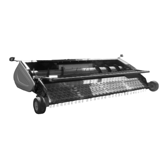
MacDon PW8 Unloading And Assembly Instructions
Pick-up header. 2019 model year
Hide thumbs
Also See for PW8:
- Operator's manual (304 pages) ,
- Operator's manual (358 pages) ,
- Unloading and assembly instructions (146 pages)
Table of Contents
Advertisement
Quick Links
Download this manual
See also:
Operator's Manual
Advertisement
Table of Contents

Related Manuals for MacDon PW8


Summary of Contents for MacDon PW8
- Page 1 Pick-Up Header Unloading and Assembly Instructions (North America) 214658 Revision A 2019 Model Year Original Instruction The harvesting specialists.
- Page 2 PW8 Pick-Up Header Published June 2018...
- Page 3 RT490 When setting up the machine or making adjustments, review and follow the recommended machine settings in all relevant MacDon publications. Failure to do so may compromise machine function and machine life and may result in a hazardous situation. NOTE: Keep your MacDon publications up-to-date.
- Page 4 List of Revisions The following list provides an account of major changes from the previous version of this document. Summary of Change Location 3.6 Setting Fixed Wheels to Field/Working Position, Updated illustration. page 25 New topic and contents created for Case IH 6.1.3 Case IH 5130/6130/7130 and 5140/6140/7140 5130/6130/7130 and 5140/6140/7140 midrange Midrange Combines, page 79...
-
Page 5: Table Of Contents
TABLE OF CONTENTS Introduction..............................i List of Revisions ............................ii Chapter 1: Safety ............................ 1 1.1 Signal Words ............................1 1.2 General Safety.............................2 1.3 Safety Signs ............................4 1.4 Safety Sign Locations...........................5 Chapter 2: Shipping Data........................13 Chapter 3: Unloading the Header ..................... 15 3.1 Unloading with a Forklift ........................15 3.2 Lowering Header ..........................17 3.3 Removing Shipping Stands.........................18... - Page 6 TABLE OF CONTENTS Chapter 5: Attaching Header to Combine ..................55 5.1 Attaching to Case IH Combine ......................55 5.2 Attaching to John Deere 60, 70, S, or T Series Combine ...............58 5.3 Attaching to New Holland CR/CX Series Combine ................62 5.4 Attaching to Versatile Combine ......................66 5.5 Removing Deck Shipping Braces ......................71 5.6 Installing Crop Deflectors........................72...
- Page 7 TABLE OF CONTENTS Adjusting Manual Header Raise/Lower Rate (John Deere S and T Series) ........112 Setting Preset Cutting Height (John Deere S and T Series)............113 6.1.8 New Holland Combines CX/CR Series (CR Series – Model Year 2014 and Earlier) ...... 115 Checking Voltage Range from Combine Cab (New Holland) ............
-
Page 9: Chapter 1: Safety
1 Safety 1.1 Signal Words Three signal words, DANGER, WARNING, and CAUTION, are used to alert you to hazardous situations. Signal words are selected using the following guidelines: DANGER Indicates an imminently hazardous situation that, if not avoided, will result in death or serious injury. WARNING Indicates a potentially hazardous situation that, if not avoided, could result in death or serious injury. -
Page 10: General Safety
SAFETY 1.2 General Safety CAUTION The following are general farm safety precautions that should be part of your operating procedure for all types of machinery. Protect yourself. • When assembling, operating, and servicing machinery, wear all protective clothing and personal safety devices that could be necessary for job at hand. - Page 11 SAFETY • Wear close-fitting clothing and cover long hair. Never wear dangling items such as scarves or bracelets. • Keep all shields in place. NEVER alter or remove safety equipment. Make sure driveline guards can rotate independently of shaft and can telescope freely. •...
-
Page 12: Safety Signs
Replace safety signs that are missing or illegible. • If original part on which a safety sign was installed is replaced, be sure repair part also bears current safety sign. • Safety signs are available from your MacDon Dealer. Figure 1.7: Operator’s Manual Decal 214658 Revision A... -
Page 13: Safety Sign Locations
SAFETY 1.4 Safety Sign Locations Figure 1.8: Header Decals – Case IH A - MD #184370 B - MD #166466 C - MD #184372 D - MD #184422 E - MD #184420 F - MD #237298 Figure 1.9: Header Decals 214658 Revision A... - Page 14 SAFETY Figure 1.10: Header Decals – John Deere A - MD #184370 B - MD #166466 C - MD #184372 D - MD #184422 E - MD #184420 F - MD #237298 Figure 1.11: Header Decals 214658 Revision A...
- Page 15 SAFETY Figure 1.12: Header Decals – New Holland A - MD #184370 B - MD #166466 C - MD #184372 D - MD #184422 E - MD #184420 F - MD #237298 Figure 1.13: Header Decals 214658 Revision A...
- Page 16 SAFETY Figure 1.14: Header Decals – Versatile A - MD #184370 B - MD #166466 C - MD #184372 D - MD #184422 E - MD #184420 F - MD #237298 Figure 1.15: Header Decals 214658 Revision A...
- Page 17 SAFETY Figure 1.16: Driveline and Hold-Down Decals – Case IH A - MD #30316 B - MD #191099 C - MD #36651 D - MD #184422 (Behind Endshield) E - MD #237229 F - MD #237254 Figure 1.17: Driveline and Hold-Down Decals 214658 Revision A...
- Page 18 SAFETY Figure 1.18: Driveline and Hold-Down Decals – John Deere A - MD #30316 B - MD #191099 C - MD #36651 D - MD #184422 (Behind Endshield) E - MD #237229 F - MD #237254 Figure 1.19: Driveline and Hold-Down Decals 214658 Revision A...
- Page 19 SAFETY Figure 1.20: Driveline and Hold-Down Decals – New Holland A - MD #30316 B - MD #191099 C - MD #36651 D - MD #184422 (Behind Endshield) E - MD #237229 F - MD #237254 Figure 1.21: Driveline and Hold-Down Decals 214658 Revision A...
- Page 20 SAFETY Figure 1.22: Driveline and Hold-Down Decals – Versatile A - MD #30316 B - MD #191099 C - MD #36651 D - MD #184422 (Behind Endshield) E - MD #237229 F - MD #237254 Figure 1.23: Driveline and Hold-Down Decals 214658 Revision A...
-
Page 21: Chapter 2: Shipping Data
2 Shipping Data The following data include shipping stands: Length (A) Width (B) Height (C) Weight 5318 mm (17 ft. 5 in.) 1000 mm (39-3/8 in.) 2579 mm (8 ft. 5-1/2 in.) 1612 kg (3550 lb.) Figure 2.1: Shipping Dimensions Weight is approximate and depends on combine completion package. -
Page 23: Chapter 3: Unloading The Header
Extra hardware is stored inside the manual storage case at the back of the header. Loose parts are strapped to the header. NOTE: MacDon recommends storing pick-up headers in the horizontal position after being received. If the units must be stored in the vertical position, ensure the storage surface is flat and hard. WARNING Be sure all persons/pets are clear when moving the header. - Page 24 UNLOADING THE HEADER To unload headers from a trailer, follow these steps: 1. Move trailer into position on level ground, and then block trailer wheels. 2. Lower trailer storage stands. 3. Approach side of trailer with forklift. 4. Adjust width of forks to line up with shipping stand pockets (A).
-
Page 25: Lowering Header
UNLOADING THE HEADER 3.2 Lowering Header IMPORTANT: These instructions are only for tipping over the unit. Lifting should only be done using a forklift and the shipping stand. 1. Attach a spreader bar (A) to forklift or equivalent. Spreader bar should have a minimum working load of 2270 kg (5000 lb.). -
Page 26: Removing Shipping Stands
UNLOADING THE HEADER 3.3 Removing Shipping Stands The removable stands are painted yellow. CAUTION Shipping stands are extremely heavy. Use caution when detaching shipping stands. NOTE: Unless otherwise specified, discard stands as well as all shipping material and hardware. 1. Remove the two bolts (A) near the top of the stand and allow the stand to rotate aft until it rests on the ground. - Page 27 UNLOADING THE HEADER 6. Remove two nuts (A). 7. Loosen two nuts (B) and remove bumper (C). 1007360 Figure 3.8: Shipping Bumper 8. Open the left endshield (A). Refer to 3.3.1 Opening Left Endshield, page 9. Remove four nuts and bolts (B). 10.
-
Page 28: Opening Left Endshield
UNLOADING THE HEADER 3.3.1 Opening Left Endshield 1. Use a slotted screwdriver to unlock endshield (B) by turning latch (A) counterclockwise until it stops (slightly more than one half turn). Figure 3.11: Endshield Closed 2. Grasp forward end of endshield (A) and pull open until support (B) engages and holds endshield in open position. - Page 29 UNLOADING THE HEADER 2. Close endshield (A) ensuring magnet (B) and stop (C) in header frame are aligned. This will ensure that latch (D) aligns with receptacle (E). NOTE: Latch (D) and magnet (B) positions are factory-set and should not require adjustment. Figure 3.14: Endshield 3.
-
Page 30: Attaching Fixed Wheels
UNLOADING THE HEADER 3.4 Attaching Fixed Wheels Headers can be ordered with either fixed wheels or caster wheels. For instructions about attaching caster wheels, refer to 3.5 Attaching Caster Wheels, page 1. Retrieve wheel assemblies (A) and bag of hardware from crate. -
Page 31: Attaching Caster Wheels
UNLOADING THE HEADER 3.5 Attaching Caster Wheels Headers can be ordered with either fixed wheels or caster wheels. For instructions about attaching fixed wheels, refer to 3.4 Attaching Fixed Wheels, page NOTE: Headers are shipped with caster wheels removed. 2. Remove bolts (A). 3. - Page 32 UNLOADING THE HEADER 6. Remove bolt (A) and rotate the caster wheel support tube (B) until the upper hole (C) is aligned. 7. Install bolt (A) into hole (C). Torque bolt to 234 Nm (173 lbf·ft). Figure 3.21: Header Wheel Right Side 8.
-
Page 33: Setting Fixed Wheels To Field/Working Position
UNLOADING THE HEADER 3.6 Setting Fixed Wheels to Field/Working Position Headers can be ordered with either fixed wheels or caster wheels. For instructions about positioning caster wheels in field/working position, refer to 3.7 Setting Caster Wheels to Field/Working Position, page Wheels must be in working position (with cog lined up with position 2 [A] on header frame) prior to setting the header on the ground. -
Page 34: Setting Caster Wheels To Field/Working Position
UNLOADING THE HEADER 3.7 Setting Caster Wheels to Field/Working Position Headers can be ordered with either fixed wheels or caster wheels. For instructions about positioning fixed wheels in field/working position, refer to 3.6 Setting Fixed Wheels to Field/Working Position, page 1. -
Page 35: Extending Hold-Down To Field/Working Position
UNLOADING THE HEADER 3.8 Extending Hold-Down to Field/Working Position Extend the hold-down into the working position as follows: 1. If necessary, lift hold-down (A) slightly to gain access to bolts (B) inside hold-down arms. NOTE: When working under the hold-down, lower the safety props and engage the securing pins. -
Page 36: Adjusting Transport Lights
UNLOADING THE HEADER 3.9 Adjusting Transport Lights Position the transport lights so they are perpendicular to the endsheet. DANGER To avoid bodily injury or death from unexpected startup of machine, always stop engine and remove key from ignition before leaving operator’s seat for any reason. 1. -
Page 37: Repositioning Driveline Storage Bracket
UNLOADING THE HEADER 3.10 Repositioning Driveline Storage Bracket 1. Remove shipping wire securing driveline to header. 2. Rotate locking disc (A) and remove driveline from bracket (B). 3. Remove the two bolts (C) securing bracket (B) to the header leg and remove the bracket. 4. - Page 38 UNLOADING THE HEADER 7. Position bracket (A) against header frame and locate the preinstalled bolt (B) into the upper slot in frame. 8. Swivel bracket (A) so that slot in bracket engages bolt (B) in lower slot in frame. 9. Tighten the two nuts. Figure 3.36: Driveline Bracket 10.
-
Page 39: Chapter 4: Reconfiguring Headers
4.1 Configuring Headers for John Deere PW8 Pick-Up Headers are configured at the factory for John Deere combine models with a 1397 mm (55 in.) feeder house. These procedures describe how to modify the header for models with a 1650 mm (65 in.) feeder house. - Page 40 RECONFIGURING HEADERS 2. Remove the four bolts (A) attaching left stripper assembly (B) to the frame, left of the header centerline (C). NOTE: For clarity, auger not shown in illustration at right. NOTE: The centerline is located where the header pans meet. Figure 4.2: Left Stripper –...
- Page 41 RECONFIGURING HEADERS 6. Remove four bolts (A) attaching right stripper assembly (B) to the frame. Figure 4.5: Right Stripper – Narrow Opening 7. Reinstall the four bolts (A) where the stripper assembly (B) mounting holes line up with the frame. Tighten bolts.
- Page 42 RECONFIGURING HEADERS 10. Move right stripper assembly (A) outboard so that dimension (B) from header centerline (C) is 700 mm (27-9/16 in.). 11. Make sure distance (D) between stripper assemblies is 1400 mm (55–1/8 in.). Figure 4.8: Right Stripper – Wide Opening 12.
-
Page 43: Removing Flighting Extensions
RECONFIGURING HEADERS 4.1.2 Removing Flighting Extensions Follow these steps to configure the auger flighting extensions for a 1651 mm (65 in.) feeder house: 1. Remove the two access covers (A) on both sides of center. 1006481 Figure 4.11: Access Holes in Auger 2. -
Page 44: Installing Auger Fingers
RECONFIGURING HEADERS 4.1.3 Installing Auger Fingers The total number of fingers installed on the auger should be 22. Follow these steps to install the extra auger fingers required to configure the header: 1. Retrieve the bag of hardware from the manual storage case located on the back of the header. 2. - Page 45 RECONFIGURING HEADERS 11. Replace access covers (A) and secure with existing screws (B). Torque to 11 Nm (95 lbf∙in). Figure 4.15: Access Cover 214658 Revision A...
-
Page 46: Configuring Headers For Case Ih
4.2 Configuring Headers for Case IH PW8 Pick-Up Headers are configured at the factory for Cas IH combine models with a 1372 mm (54 in.) feeder house. These procedures describe how to modify the header for models with a 1156 mm (46 in.) feeder house. - Page 47 RECONFIGURING HEADERS 3. Move the left stripper assembly (A) inboard so that the distance (B) from the stripper assembly to the header centerline (C) is 578 mm (22-3/4 in.). NOTE: The centerline is located where the header pans meet. Figure 4.18: Narrow Opening 4.
- Page 48 RECONFIGURING HEADERS 6. Move right stripper assembly (A) inboard so dimension (B) from header centerline (C) is 578 mm (22-3/4 in.). 7. Make sure the distance (D) between stripper assemblies is 1156 mm (45-1/2 in.). Figure 4.21: Narrow Opening 8. Reinstall the four bolts (A) where stripper assembly (B) mounting holes line up with the frame.
-
Page 49: Configuring Headers For New Holland Cx
4.3 Configuring Headers for New Holland CX PW8 Pick-Up Headers are configured at the factory for New Holland combine models with a 1270 mm (50 in.) feeder house. These procedures describe how to modify the header for model CX with a 1524 mm (60 in.) feeder house. - Page 50 RECONFIGURING HEADERS 3. Move left stripper assembly (A) outboard so the distance (B) from the stripper assembly to header centerline (C) is 700 mm (27-9/16 in.). NOTE: The centerline is located where the header pans meet. Figure 4.26: Left Stripper – Wide Opening 4.
- Page 51 RECONFIGURING HEADERS 7. Move right stripper assembly (A) outboard so that dimension (B) from header centerline (C) is 700 mm (27-9/16 in.). 8. Make sure distance (D) between stripper assemblies is 1400 mm (55-1/8 in.). Figure 4.29: Right Stripper – Wide Opening 9.
-
Page 52: Removing Flighting Extensions
RECONFIGURING HEADERS 4.3.2 Removing Flighting Extensions Follow these steps to configure the auger flighting extensions for a 1651 mm (65 in.) feeder house: 1. Remove the two access covers (A) on both sides of center. 1006481 Figure 4.32: Access Holes in Auger 2. -
Page 53: Installing Auger Fingers
RECONFIGURING HEADERS 4.3.3 Installing Auger Fingers The total number of fingers installed on the auger should be 22. Follow these steps to install the extra auger fingers required to configure the header: 1. Retrieve the bag of hardware from the manual storage case located on the back of the header. 2. - Page 54 RECONFIGURING HEADERS 11. Replace access covers (A) and secure with existing screws (B). Torque to 11 Nm (95 lbf∙in). Figure 4.36: Access Cover 214658 Revision A...
-
Page 55: Configuring Headers For New Holland Cr
4.4 Configuring Headers for New Holland CR PW8 Pick-Up Headers are configured at the factory for New Holland combine models with a 1270 mm (50 in.) feeder house. These procedures describe how to modify the header for models with a 1016 mm (40 in.) feeder house. - Page 56 RECONFIGURING HEADERS 3. Move the left stripper assembly (A) inboard so that the distance (B) from the stripper assembly to the header centerline (C) is 417 mm (16-7/16 in.). NOTE: The centerline is located where the header pans meet. Figure 4.39: Narrow Opening 4.
- Page 57 RECONFIGURING HEADERS 7. Move the right stripper assembly (A) inboard so that dimension (B) from header centerline (C) is 417 mm (16-7/16 in.). 8. Ensure distance (D) between stripper assemblies is 834 mm (32-13/16 in.). Figure 4.42: Narrow Opening 9. Reinstall the four bolts (A) where stripper assembly (B) mounting holes line up with the frame.
-
Page 58: Installing Flighting Extensions
RECONFIGURING HEADERS 4.4.2 Installing Flighting Extensions Follow these steps to install the long flighting extensions required for a 1 m (40 in.) feeder house: 1. Remove the two flighting extensions (A) that are strapped to the auger. Figure 4.45: Left Extension – Right Opposite 2. - Page 59 RECONFIGURING HEADERS 4. Retrieve the hardware provided in the manual storage case. 5. Place new flighting extension (A) on auger, ensuring new flighting rests on the outboard side of existing flighting (B). 6. Secure flighting extension (A) to auger with existing hardware and additional M8 x 20 bolts (C) and locknuts provided in hardware bag.
-
Page 60: Removing Auger Fingers
RECONFIGURING HEADERS 4.4.3 Removing Auger Fingers Follow these steps to configure the auger fingers for a New Holland 1 m (40 in.) feeder house: NOTE: There should be 16 fingers on the auger. 1. Remove the two covers (A) on each side of the auger to access the auger fingers (B). - Page 61 RECONFIGURING HEADERS 9. Position plug (B) in hole from inside the auger and secure with M6 x 20 long hex socket screws (A). 10. Torque screws to 8.5 Nm (75 lbf∙in). 11. Repeat Step 6, page 52 to Step 10, page 53 for the other plastic guide.
-
Page 62: Adjusting Stripper Plate Clearance
RECONFIGURING HEADERS 4.5 Adjusting Stripper Plate Clearance 1. Loosen nuts (A) on stripper plate (B), and adjust the stripper plate to achieve clearance (C) of 3–8 mm (1/8–5/16 in.). 2. Tighten nuts (A). 3. Recheck clearance. Figure 4.54: Stripper Plate Clearance 214658 Revision A... -
Page 63: Chapter 5: Attaching Header To Combine
5 Attaching Header to Combine This section includes instructions for attaching PW8 headers to the combines listed below. Combine Refer to Case IH 5.1 Attaching to Case IH Combine, page 55 John Deere 5.2 Attaching to John Deere 60, 70, S, or T Series Combine, page 58 New Holland CR, CX Series 5.3 Attaching to New Holland CR/CX Series Combine, page 62... - Page 64 ATTACHING HEADER TO COMBINE 5. Lift lever (A) on header at left side of feeder house and push handle (B) on combine to engage locks (C) on both sides of the feeder house. 6. Push down on lever (A) so that slot in lever engages handle (B) to lock handle in place.
- Page 65 ATTACHING HEADER TO COMBINE 10. Pull back collar (A) on end of driveline and push onto combine output shaft (B) until collar locks. Figure 5.5: Attaching Driveline 11. Open cover (A) on header receptacle. 12. Push in lock button (B) and pull handle (C) upward to fully open position.
-
Page 66: Attaching To John Deere 60, 70, S, Or T Series Combine
ATTACHING HEADER TO COMBINE 5.2 Attaching to John Deere 60, 70, S, or T Series Combine DANGER To avoid bodily injury or death from unexpected startup of machine, always stop engine and remove key from ignition before leaving operator’s seat for any reason. 1. - Page 67 ATTACHING HEADER TO COMBINE 6. Rotate disc (B) on header driveline storage hook (A) and remove driveline from hook. Figure 5.11: Driveline in Storage Position 7. Pull back collar (A) on end of driveline and slide driveline on feeder house driveshaft until the collar locks.
- Page 68 ATTACHING HEADER TO COMBINE 10. Pull handle (A) on header to release multicoupler (B) from storage position, remove coupler, and push handle back into header to store. Figure 5.14: Releasing Coupler 11. Place coupler (A) onto combine receptacle. 12. Pull out knob (B) to release handle, and pull handle (C) to engage pins in coupler.
- Page 69 ATTACHING HEADER TO COMBINE 13. Pull handle (A) from vertical to fully horizontal position to fully engage multicoupler and to extend pins (B) at the base of the feeder house into locking plates (C). Knob (D) will engage lock handle. Figure 5.16: Locking Feeder House NOTE: If handle does not move to fully horizontal position,...
-
Page 70: Attaching To New Holland Cr/Cx Series Combine
ATTACHING HEADER TO COMBINE 5.3 Attaching to New Holland CR/CX Series Combine DANGER To avoid bodily injury or death from unexpected startup of machine, always stop engine and remove key from ignition before leaving operator’s seat for any reason. 1. Pull handle (A) on combine to raise hooks (B) on both sides of the feeder house. - Page 71 ATTACHING HEADER TO COMBINE 4. Lift lever (A) on header at left side of feeder house and push handle (B) on combine so that hooks (C) engage pins (D) on both sides of the feeder house. 5. Push down on lever (A) so that slot in lever engages handle (B) to lock handle in place.
- Page 72 ATTACHING HEADER TO COMBINE 9. Pull back collar (B) on end of driveline and push onto combine output shaft (A) until collar locks. Figure 5.22: Attaching Driveline 10. Open cover (A). 11. Push in lock button (B) and pull handle (C) halfway up to open position.
- Page 73 ATTACHING HEADER TO COMBINE 13. Position coupler onto header receptacle (A) and push handle (B) downward to engage pins into receptacle. 14. Push handle (B) to closed position until lock button (C) snaps out. 15. Open cover (D) on header electrical receptacle. 16.
-
Page 74: Attaching To Versatile Combine
ATTACHING HEADER TO COMBINE 5.4 Attaching to Versatile Combine DANGER To avoid bodily injury or death from unexpected startup of machine, always stop engine and remove key from ignition before leaving operator’s seat for any reason. 1. Check that pins (A) at lower corners of header opening are retracted. - Page 75 ATTACHING HEADER TO COMBINE 7. Measure the misalignment between pin (A) and feeder house receptacle (B). 8. Lower header to the ground until the feeder house disengages the top beam. Figure 5.29: Feeder House Lock 9. Loosen the seven bolts (A) along top beam (B) on the auger side of the header.
- Page 76 ATTACHING HEADER TO COMBINE 11. Move support channel (A) according to measurement in Step to achieve proper alignment of locking pin and feeder house receptacle. Refer to Figure 7, page 12. Tighten all bolts. Figure 5.32: Top Beam (Rear View) 13.
- Page 77 ATTACHING HEADER TO COMBINE 15. Pull back collar (A) at the end of the driveline and push onto combine output shaft (B) until the collar locks. Figure 5.35: Driveline 16. Open cover (A) on header receptacle. 17. Push in lock button (B) and pull handle (C) upward to fully open position.
- Page 78 ATTACHING HEADER TO COMBINE 19. Position coupler (A) onto header receptacle and push handle (B) downward to engage coupler pins into receptacle. 20. Push handle to closed position until lock button (C) snaps out. 21. Open cover (D) on the header electrical receptacle. 22.
-
Page 79: Removing Deck Shipping Braces
ATTACHING HEADER TO COMBINE 5.5 Removing Deck Shipping Braces DANGER To avoid bodily injury or death from unexpected startup of machine, always stop engine and remove key from ignition before leaving operator’s seat for any reason. 1. Start combine. 2. Relieve load on support bolts (A) and (B) by raising and lowering the feeder house until bolts are loose. -
Page 80: Installing Crop Deflectors
ATTACHING HEADER TO COMBINE 5.6 Installing Crop Deflectors Crop deflectors are provided to reduce the build up of stems under the hold-down support arm pivot. If crop deflectors will not be installed, remove them from the auger drive compartment and store them in the combine cab or another suitable location. -
Page 81: Chapter 6: Predelivery Inspection
NOTE: This section does not apply to Versatile combines. Sensors installed at each end of the PW8 Pick-Up Header send a signal to the combine allowing it to maintain a consistent cutting height as the header follows ground contours. PW8 Pick-Up Headers are factory-equipped for AHHC; however, before using AHHC feature, you must do the following: 1. -
Page 82: Ahhc Sensor Operation
PREDELIVERY INSPECTION 6.1.1 AHHC Sensor Operation The position sensors supplied with the auto header height control (AHHC) system are 1000 ohm (1 k) industrial series variable resistor consisting of a sealed unit with a three-pin connection point (A) and two mounting holes (B). A signal wire is connected internally to a movable wiper (C) that sweeps across a high resistance filament band. -
Page 83: Manually Checking Voltage Range
PREDELIVERY INSPECTION Manually Checking Voltage Range In some combines, output voltage range of auto header height control (AHHC) sensors can be checked from the cab. For instructions, refer to the combine operator’s manual or AHHC instructions later in this document. 1. - Page 84 PREDELIVERY INSPECTION 7. Remove two bolts (A) from access panel (B). 8. Remove access panel (B). Figure 6.4: Right Access Panel 9. Locate right height sensor (A). NOTE: Sensor may not be exactly as shown, and view of harness is from inboard side of endsheet. 10.
-
Page 85: Adjusting Header Height Sensor Voltage Range (Left Side)
PREDELIVERY INSPECTION Adjusting Header Height Sensor Voltage Range (Left Side) DANGER To avoid bodily injury or death from unexpected startup of machine, always stop engine and remove key from ignition before leaving operator’s seat for any reason. 1. Lower header to ground, shut down combine, and remove key from ignition. 2. - Page 86 PREDELIVERY INSPECTION 4. Remove two bolts (A) from access panel (B). 5. Remove access panel (B). Figure 6.8: Right Access Panel 6. Loosen nuts (A). 7. Rotate sensor (B) until desired voltage range is achieved. Refer to 6.1.2 Height Sensor Output Voltage Range –...
-
Page 87: Case Ih 5130/6130/7130 And 5140/6140/7140 Midrange Combines
PREDELIVERY INSPECTION 6.1.3 Case IH 5130/6130/7130 and 5140/6140/7140 Midrange Combines Setting up the Header on the Combine Display (Case IH 5130/6130/7130; 5140/6140/7140) 1. On the main page of the combine display, select TOOLBOX (A). Figure 6.11: Case IH Combine Display 2. -
Page 88: Checking Voltage Range From Combine Cab (Case Ih 5130/6130/7130; 5140/6140/7140)
PREDELIVERY INSPECTION 6. From the BELT DRIVE TYPE menu (A), select • 1 - for most pick-up headers • 2 - for 4.9 m (16 ft.) Rake-Up pick-up headers • 3 - for SwathMaster pick-up headers NOTE: Proper belt drive selection optimizes auto-belt to ground speed. - Page 89 PREDELIVERY INSPECTION 3. Select SETTINGS (A). The SETTINGS page opens. 4. From the GROUP menu (B), select HEADER. Figure 6.16: Case IH Combine Display 5. From the PARAMETER menu, select LEFT HEIGHT/ TILT SENSOR (A). Figure 6.17: Case IH Combine Display 6.
-
Page 90: Calibrating Auto Header Height Control (Case Ih 5130/6130/7130, 5140/6140/7140)
PREDELIVERY INSPECTION Calibrating Auto Header Height Control (Case IH 5130/6130/7130, 5140/6140/7140) NOTE: This procedure applies to combines with a software version below 28.00. For instructions on calibrating the AHHC for combines with software version 28.00 or above, refer to Calibrating Auto Header Height Control (Case Combines with Version 28.00 or Higher Software), page NOTE: Changes may have been made to the combine controls or display since this document was published. - Page 91 PREDELIVERY INSPECTION 4. Manually raise or lower header to a second desired cutting height. 5. Press 2 on button (A). A yellow light next to the button will illuminate. Figure 6.21: Case Combine Console Up and down arrows should now appear in the MANUAL HEIGHT box (A) on the RUN 1 page on the combine display.
- Page 92 PREDELIVERY INSPECTION 7. The maximum working height can be adjusted on the HEADER SETUP page on the combine display. Enter the desired height in the MAXIMUM WORKING HEIGHT field (A). Figure 6.24: Case Combine Display – Header Setup Page 8. If you need to change the position of one of the presets, you can fine tune this setting with button (A) on the combine console.
-
Page 93: Case Ih 7010/8010, 7120/8120/9120, 7230/8230/9230, And 7240/8240/9240 Combines
PREDELIVERY INSPECTION 6.1.4 Case IH 7010/8010, 7120/8120/9120, 7230/8230/9230, and 7240/8240/9240 Combines Checking Voltage Range from Combine Cab (Case 8010) NOTE: Changes may have been made to combine controls or display since this document was published. Refer to combine operator’s manual for updates. CAUTION Check to be sure all bystanders have cleared the area. - Page 94 PREDELIVERY INSPECTION 4. Select HDR HEIGHT/TILT (A). The SENSOR page displays. 1003678 Figure 6.28: Case 8010 Combine Display 5. Select LEFT SEN (A). The exact voltage is displayed. Raise and lower header to see full range of voltage readings. Figure 6.29: Case 8010 Combine Display 6.
-
Page 95: Checking Voltage Range From Combine Cab
PREDELIVERY INSPECTION Checking Voltage Range from Combine Cab (Case IH 7010/8010; 7120/8120/9120; 7230/8230/9230; 7240/8240/9240) NOTE: Changes may have been made to the combine controls or display since this document was published. Refer to the combine operator’s manual for updates. CAUTION Check to be sure all bystanders have cleared the area. - Page 96 PREDELIVERY INSPECTION 5. Select HEADER HEIGHT/TILT (A). The PARAMETER page opens. Figure 6.33: Case IH Combine Display 6. Select LEFT HEADER HEIGHT SEN (A), and then select GRAPH button (B). The exact voltage is displayed at top of the page. Raise and lower the header to see the full range of voltage readings.
-
Page 97: Calibrating Auto Header Height Control
PREDELIVERY INSPECTION Calibrating Auto Header Height Control (Case IH 7010/8010; 7120/8120/9120; 7230/8230/9230; 7240/8240/9240) NOTE: This procedure applies to combines with a software version below 28.00. For instructions on calibrating the AHHC for combines with software version 28.00 or above, refer to Calibrating Auto Header Height Control (Case Combines with Version 28.00 or Higher Software), page NOTE:... - Page 98 PREDELIVERY INSPECTION 6. Select YES (A) from the REEL FORE-BACK list (if applicable). 7. Set HEIGHT SENSITIVITY (B) to desired value. The recommended starting point is 180. Figure 6.37: Case IH Combine Display 8. Select YES for FORE-AFT CONTROL (A) and HDR FORE-AFT TILT (B) (if applicable).
-
Page 99: Software)
PREDELIVERY INSPECTION Calibrating Auto Header Height Control (Case Combines with Version 28.00 or Higher Software) NOTE: Changes may have been made to combine controls or display since this document was published. Refer to combine operator’s manual for updates. 1. Select TOOLBOX on the MAIN page, and then select HEADER SETUP. - Page 100 PREDELIVERY INSPECTION 9. Select CALIBRATION on the combine display, and press the right arrow navigation key to enter the information box. 10. Select HEADER (A), and press ENTER. The CALIBRATION dialog box opens. NOTE: You can use up and down navigation keys to move between options.
-
Page 101: Setting Preset Cutting Height
PREDELIVERY INSPECTION Setting Preset Cutting Height (Case 7010/8010, 7120/8120/9120, 7230/8230/9230, 7240/8240/9240) To set preset cutting height, follow these steps: NOTE: Changes may have been made to the combine controls or display since this document was published. Refer to the combine operator’s manual for updates. CAUTION Check to be sure all bystanders have cleared the area. -
Page 102: John Deere 60 Series Combines
PREDELIVERY INSPECTION 6.1.5 John Deere 60 Series Combines Checking Voltage Range from Combine Cab (John Deere 60 Series) The auto header height sensor output must be within a specific range, or feature will not work properly. Refer to 6.1.2 Height Sensor Output Voltage Range – Combine Requirements, page 74 for voltage limits. -
Page 103: Calibrating Auto Header Height Control (John Deere 60 Series)
PREDELIVERY INSPECTION 7. Check sensor reading on monitor. 8. Raise header so it is just off ground and check sensor reading again. 6.1.2 Height Sensor Output Voltage Range – 9. If sensor voltage is not within low and high limits shown in Combine Requirements, page 74, or if range between low and high limits is insufficient, you need to make adjustments. - Page 104 PREDELIVERY INSPECTION 3. Press UP or DOWN buttons until HDR appears on monitor. 4. Press ENTER button. HDR H-DN appears on monitor. 5. Fully lower feeder house to ground. NOTE: You may need to hold HEADER DOWN switch for a few seconds to ensure feeder house is fully lowered.
-
Page 105: Turning Off Accumulator (John Deere 60 Series)
PREDELIVERY INSPECTION Turning Off Accumulator (John Deere 60 Series) NOTE: Changes may have been made to combine controls or display since this document was published. Refer to combine operator’s manual for updates. 1. Press DIAGNOSTIC button (A) on monitor. DIA appears on the monitor. -
Page 106: Setting Sensing Grain Header Height To 50 (John Deere 60 Series)
NOTE: Do NOT use active header float function (A) in combination with MacDon auto header height control (AHHC)—the two systems will counteract one another. The header symbol (B) on display should NOT have a wavy line under it and should appear exactly as shown on Active Header Control Display in Figure 6.53,... -
Page 107: Setting Sensitivity Of Auto Header Height Control (John Deere 60 Series)
PREDELIVERY INSPECTION Setting Sensitivity of Auto Header Height Control (John Deere 60 Series) This is also known as dead band adjustment. NOTE: Changes may have been made to combine controls or display since this document was published. Refer to combine operator’s manual for updates. 1. -
Page 108: Adjusting Threshold For Drop Rate Valve (John Deere 60 Series)
PREDELIVERY INSPECTION Adjusting Threshold for Drop Rate Valve (John Deere 60 Series) This procedure explains how to adjust the point at which the restrictor valve opens and allows full flow to lift cylinders. NOTE: Changes may have been made to combine controls or display since this document was published. Refer to combine operator’s manual for updates. -
Page 109: John Deere 70 Series Combines
PREDELIVERY INSPECTION 6.1.6 John Deere 70 Series Combines Checking Voltage Range from Combine Cab (John Deere 70 Series) The auto header height sensor output must be within a specific range, or feature will not work properly. Refer to 6.1.2 Height Sensor Output Voltage Range – Combine Requirements, page 74 for voltage limits. -
Page 110: Calibrating Auto Header Height Control (John Deere 70 Series)
PREDELIVERY INSPECTION Calibrating Auto Header Height Control (John Deere 70 Series) NOTE: Changes may have been made to combine controls or display since this document was published. Refer to combine operator’s manual for updates. CAUTION Check to be sure all bystanders have cleared the area. 1. -
Page 111: Setting Sensitivity Of Auto Header Height Control (John Deere 70 Series)
PREDELIVERY INSPECTION Figure 6.59: John Deere Combine Control Console A - Scroll Knob B - Check Mark Button Setting Sensitivity of Auto Header Height Control (John Deere 70 Series) NOTE: Changes may have been made to combine controls or display since this document was published. Refer to combine operator’s manual for updates. - Page 112 PREDELIVERY INSPECTION NOTE: The numbers depicted on displays in these illustrations are for reference purposes only; they are not intended to represent specific settings for your equipment. Figure 6.61: John Deere Combine Display 214658 Revision A...
-
Page 113: Adjusting Manual Header Raise/Lower Rate (John Deere 70 Series)
PREDELIVERY INSPECTION Adjusting Manual Header Raise/Lower Rate (John Deere 70 Series) NOTE: Changes may have been made to combine controls or display since this document was published. Refer to combine operator’s manual for updates. 1. Press button (A) and current raise/lower rate setting will appear on monitor (the lower reading, slower rate). -
Page 114: John Deere S And T Series Combines
PREDELIVERY INSPECTION 6.1.7 John Deere S and T Series Combines Checking Voltage Range from Combine Cab (John Deere S and T Series) The auto header height sensor output must be within a specific range, or feature will not work properly. Refer to 6.1.2 Height Sensor Output Voltage Range –... - Page 115 PREDELIVERY INSPECTION NOTE: The feeder house fore-aft tilt controls can be changed to work with buttons E and F by pressing hydro handle icon (A) and then selecting FEEDER HOUSE FORE/AFT TILT from drop-down menu (B) on combine display. Figure 6.65: John Deere Combine Display To calibrate feeder house fore-aft tilt range, follow these steps: 1.
- Page 116 PREDELIVERY INSPECTION 3. Press arrow (A) to cycle up through calibration options and select FEEDER HOUSE FORE/AFT TILT RANGE. Figure 6.68: John Deere Combine Display 4. Press ENTER icon (A). Figure 6.69: John Deere Combine Display 5. Follow instructions that appear on combine display. As you proceed through calibration process, display will automatically update to show next step.
-
Page 117: Calibrating Auto Header Height Control (John Deere S And T Series)
PREDELIVERY INSPECTION Calibrating Auto Header Height Control (John Deere S and T Series) NOTE: Changes may have been made to combine controls or display since this document was published. Refer to combine operator’s manual for updates. 1. Press DIAGNOSTIC icon (A) on main page of monitor. The CALIBRATION page appears. - Page 118 PREDELIVERY INSPECTION 5. Press icon (A) with either FEEDER HOUSE SPEED or HEADER selected and icon will turn green. Figure 6.74: John Deere Combine Display 6. Click button (A) and instructions will appear on screen to guide you through remaining calibration steps. NOTE: If an error code appears during calibration, one or both sensors are out of voltage range and will require...
-
Page 119: Setting Sensitivity Of Auto Header Height Control (John Deere S And T Series)
PREDELIVERY INSPECTION Setting Sensitivity of Auto Header Height Control (John Deere S and T Series) NOTE: Changes may have been made to combine controls or display since this document was published. Refer to combine operator’s manual for updates. 1. Press button (A) twice and current sensitivity setting will appear on combine display. -
Page 120: Adjusting Manual Header Raise/Lower Rate (John Deere S And T Series)
PREDELIVERY INSPECTION Adjusting Manual Header Raise/Lower Rate (John Deere S and T Series) NOTE: Changes may have been made to the combine controls or display since this document was published. Refer to combine operator’s manual for updates. 1. Press button (A) and current sensitivity setting will appear on monitor. -
Page 121: Setting Preset Cutting Height (John Deere S And T Series)
PREDELIVERY INSPECTION Setting Preset Cutting Height (John Deere S and T Series) NOTE: Changes may have been made to combine controls or display since this document was published. Refer to combine operator’s manual for updates. 1. Press COMBINE – HEADER SETUP icon (A) on main page. - Page 122 PREDELIVERY INSPECTION 4. Turn on header engagement switch (A) and move header to desired preset position. 5. Position can be fine-tuned with HEADER HEIGHT PRESSURE CONTROL DIAL (B). Figure 6.83: Combine Control Console 6. Hold joystick button 2 (B) until the AHHC icon flashes on monitor.
-
Page 123: New Holland Combines Cx/Cr Series (Cr Series - Model Year 2014 And Earlier)
PREDELIVERY INSPECTION 6.1.8 New Holland Combines CX/CR Series (CR Series – Model Year 2014 and Earlier) NOTE: For New Holland CR models 6.80, 6.90, 7.90, 8.90, 9.90, and 10.90, refer to 6.1.9 New Holland Combines (CR Series – Model Year 2015 and Later), page 125. - Page 124 PREDELIVERY INSPECTION 5. Select HEADER HEIGHT/TILT (A). The PARAMETER page displays. Figure 6.88: New Holland Combine Display 6. Select LEFT HEADER HEIGHT SEN (A), and then select GRAPH button (B). The exact voltage is displayed at top of page. 7. Raise and lower header to see full range of voltage readings.
-
Page 125: Engaging Auto Header Height Control (New Holland Cr/Cx Series)
PREDELIVERY INSPECTION Engaging Auto Header Height Control (New Holland CR/CX Series) NOTE: Changes may have been made to the combine controls or display since this document was published. Refer to the combine operator’s manual for updates. 1. Select HEADER LATERAL FLOAT on combine display, and press ENTER. -
Page 126: Calibrating Auto Header Height Control (New Holland Cr/Cx Series)
PREDELIVERY INSPECTION Calibrating Auto Header Height Control (New Holland CR/CX Series) NOTE: Changes may have been made to the combine controls or display since this document was published. Refer to the combine operator’s manual for updates. CAUTION Check to be sure all bystanders have cleared the area. Check the following conditions before starting the header calibration procedure: •... - Page 127 PREDELIVERY INSPECTION 3. Follow the calibration steps in the order that they appear in the dialog box. As you proceed through the calibration process, the display will automatically update to show the next step. NOTE: Pressing the ESC key during any of the steps or letting the system sit idle for more than 3 minutes will stop the calibration process.
- Page 128 PREDELIVERY INSPECTION Calibrating Maximum Stubble Height This procedure describes how to calibrate the area counter to stop or start counting at the correct height. Program header to a height that will never be reached while cutting. The area counter will stop counting when header is above programmed height, and will begin counting when header is below programmed height.
-
Page 129: Adjusting Header Raise Rate (New Holland Cr/Cx Series)
PREDELIVERY INSPECTION Adjusting Header Raise Rate (New Holland CR/CX Series) If necessary, header raise rate (the first speed on HEADER HEIGHT rocker switch of multifunctional handle) can be adjusted. NOTE: Changes may have been made to the combine controls or display since this document was published. Refer to combine operator’s manual for updates. -
Page 130: Setting Sensitivity Of Auto Header Height Control To 200 (New Holland Cr/Cx Series)
PREDELIVERY INSPECTION Setting Sensitivity of Auto Header Height Control to 200 (New Holland CR/CX Series) NOTE: Changes may have been made to the combine controls or display since this document was published. Refer to combine operator’s manual for updates. CAUTION Check to be sure all bystanders have cleared the area. -
Page 131: Configuring Reel Fore-Aft, Header Tilt, And Header Type (New Holland Cr Series)
PREDELIVERY INSPECTION 5. To change one of saved header height set points while combine is in use, use HEADER HEIGHT AND HEADER LATERAL FLOAT rocker switch (A) (slow up/down) to raise or lower header to desired value. Press AUTOMATIC HEADER HEIGHT CONTROL button (B) for a minimum of 2 seconds to store new height position. - Page 132 Figure 6.103: New Holland Combine Display There are now two buttons for ON GROUND presets. The toggle switch from previous models is configured as shown. MacDon headers require the first two buttons (A) and (B). The third button (C) is not configured.
-
Page 133: New Holland Combines (Cr Series - Model Year 2015 And Later)
PREDELIVERY INSPECTION 6.1.9 New Holland Combines (CR Series – Model Year 2015 and Later) This section applies only to 2015 and later CR models (6.80, 6.90, 7.90, 8.90, 9.90, and 10.90). For other 6.1.8 New Holland Combines CX/CR Series (CR Series – Model Year 2014 New Holland combine models, refer to and Earlier), page 115. - Page 134 PREDELIVERY INSPECTION 5. Select HEADER SUB TYPE drop-down arrow (A). The HEADER SUB TYPE dialog box displays. Figure 6.107: New Holland Combine Display 6. Select 80/90 (A). Figure 6.108: New Holland Combine Display 7. Select HEAD 2 (A). The HEADER SETUP 2 page displays.
- Page 135 PREDELIVERY INSPECTION 8. Select AUTOFLOAT drop-down arrow and set AUTOFLOAT to INSTALLED (A). 9. Select AUTO HEADER LIFT drop-down arrow and set AUTO HEADER LIFT to INSTALLED (B). NOTE: With AUTO HEADER LIFT installed and AHHC engaged, header will lift up automatically when you pull back on hydro handle.
-
Page 136: Checking Voltage Range From Combine Cab (New Holland Cr Series)
PREDELIVERY INSPECTION Checking Voltage Range from Combine Cab (New Holland CR Series) NOTE: Changes may have been made to the combine controls or display since this document was published. Refer to the combine operator’s manual for updates. CAUTION Check to be sure all bystanders have cleared the area. 1. - Page 137 PREDELIVERY INSPECTION 4. Select HEADER HEIGHT/TILT (A) from GROUP drop-down menu. 5. Select HEADER HEIGHT SENS. L (B) from PARAMETER drop-down menu. Figure 6.114: New Holland Combine Display 6. Select GRAPH (A). The exact voltage (B) is displayed at top of page. 7.
-
Page 138: Calibrating Auto Header Height Control (New Holland Cr Series)
PREDELIVERY INSPECTION Calibrating Auto Header Height Control (New Holland CR Series) NOTE: Changes may have been made to the combine controls or display since this document was published. Refer to the combine operator’s manual for updates. CAUTION Check to be sure all bystanders have cleared the area. Check the following conditions before starting the header calibration procedure: •... - Page 139 PREDELIVERY INSPECTION 2. Select CALIBRATION drop-down arrow (A). Figure 6.117: New Holland Combine Display 3. Select HEADER (A) from the list of calibration options. Figure 6.118: New Holland Combine Display 4. Follow calibration steps in the order they appear on screen.
- Page 140 PREDELIVERY INSPECTION 5. When all steps have been completed, the CALIBRATION COMPLETED message is displayed on screen. NOTE: If the float was set heavier to complete the ground calibration procedure, return it to the recommended operating float after completing calibration. Figure 6.120: New Holland Combine Display 214658 Revision A...
-
Page 141: Setting Auto Height (New Holland Cr Series)
The console has two buttons used for auto height presets. The toggle switch that was present on previous models is now configured as shown at right. MacDon headers only require first two buttons (A) and (B). The third button (C) is not configured. - Page 142 PREDELIVERY INSPECTION 3. Select RUN tab that shows MANUAL HEIGHT. NOTE: The MANUAL HEIGHT field may appear on any of RUN tabs. When an auto height set point button is pressed, display will change to AUTO HEIGHT (A). 4. Lower header to ground. 5.
-
Page 143: Setting Maximum Work Height (New Holland Cr Series)
PREDELIVERY INSPECTION Setting Maximum Work Height (New Holland CR Series) This procedure applies only to 2015 and later CR models (6.80, 6.90, 7.90, 8.90, 9.90, and 10.90). 1. Select TOOLBOX (A) on main page. The TOOLBOX page displays. Figure 6.124: New Holland Combine Display 2. -
Page 144: Wheels And Tires
PREDELIVERY INSPECTION 6.2 Wheels and Tires There are two wheels and tires on the PW8 Combine Pick-Up Header, one on each side of the header. DANGER • Never install a tube in a cracked wheel rim. • Never weld a wheel rim. -
Page 145: Checking Draper Belt Tension
PREDELIVERY INSPECTION 6.3 Checking Draper Belt Tension Draper tension is factory-set but should be checked before operating. DANGER To avoid bodily injury or death from unexpected startup of machine, always stop engine and remove key from ignition before leaving operator’s seat for any reason. NOTE: Drapers may be sticky when new. -
Page 146: Adjusting Front Draper Belt Tension
PREDELIVERY INSPECTION 6.3.1 Adjusting Front Draper Belt Tension Draper belt tension is factory-set, but it should be checked before operating. Figure 6.128: Front Deck Adjusting Bolt Locations The stepped position indicator gauges are used to precisely align each side of the front and rear decks. Each notch (A) represents an adjustment of 1 mm (3/64 in.). - Page 147 PREDELIVERY INSPECTION 3. Turn adjuster nut (A) to set the draper tension. Proper tension is achieved when the draper lines up with indicator notch (B). IMPORTANT: Do NOT tighten draper above the indicator notch (B). Drapers only need to be tight enough to prevent slippage.
-
Page 148: Adjusting Rear Draper Belt Tension
PREDELIVERY INSPECTION 6.3.2 Adjusting Rear Draper Belt Tension 1. Loosen two clamp bolts (A) on the left side. 2. Loosen jam nut (B). 3. Turn adjuster nut (C) to set draper tension. Proper tension is achieved when the draper lines up with indicator notch (D). -
Page 149: Lubrication
PREDELIVERY INSPECTION 6.4 Lubrication 6.4.1 Lubricating the Header DANGER To avoid bodily injury or death from unexpected startup of machine, always stop engine and remove key from ignition before leaving operator’s seat for any reason. • Use the recommended lubricant specified in the pick-up header operator’s manual. •... -
Page 150: Lubricating Auger Drive Chain
PREDELIVERY INSPECTION 6.4.2 Lubricating Auger Drive Chain DANGER To avoid bodily injury or death from unexpected startup of machine, always stop engine and remove key from ignition before leaving operator’s seat for any reason. 1. Lower header to the ground, shut down the combine, and remove the key from the ignition. 2. -
Page 151: Greasing Points
PREDELIVERY INSPECTION 6.4.3 Greasing Points Figure 6.138: Greasing Points A - Driveline Slip-Joint B - Driveline Guard (Both Ends) C - Driveline Clutch 214658 Revision A... -
Page 152: Manuals
6.5 Manuals 1. Remove cable tie on manual case (A), and open case. 2. Check that case contains the following manuals: • PW8 Pick-Up Header Operator’s Manual • PW8 Pick-Up Header Parts Catalog 3. Return manuals to the case. 4. Remove red and yellow stripe decals from case and set aside. -
Page 153: Installing Endshield Decals
PREDELIVERY INSPECTION 6.6 Installing Endshield Decals Red and yellow stripe decals for the right and left header endshields are provided in the manual case. Select the stripe decals matching your combine color and follow the installation instructions. 1. Clean and dry the installation area outlined by the black shadow (A) on left endshield. -
Page 154: Running Up The Header
PREDELIVERY INSPECTION 6.7 Running up the Header CAUTION Never start or move the machine until you are sure all bystanders have cleared the area. CAUTION Clear the area of other people, pets, etc. Keep children away from machinery. Walk around the machine to be sure no one is under, on, or close to the header. -
Page 155: Chapter 7: Reference
7 Reference 7.1 Definitions The following definitions and acronyms may be used in this manual: Term Definition American Petroleum Institute ASTM American Society of Testing and Materials Bolt A headed and externally threaded fastener that is designed to be paired with a nut CGVW Combined gross vehicle weight Finger tight is a reference position where sealing surfaces or components are... - Page 156 REFERENCE Term Definition T.F.F.T. Turns from finger tight The product of a force X lever arm length, usually measured in Newton-meters (Nm) Torque or foot-pounds (lbf∙ft). A tightening procedure where the fitting is assembled to a precondition (finger tight) Torque angle and then the nut is turned further a number of degrees or a number of flats to achieve its final position.
-
Page 157: Conversion Chart
REFERENCE 7.2 Conversion Chart Table 7.1 Conversion Chart Quantity SI Units (Metric) Factor US Customary Units (Standard) Unit Name Abbreviation Unit Name Abbreviation acre acres Area hectare x 2.4710 = US gallons per minute gpm Flow liters per minute L/min x 0.2642 = Force Newton... -
Page 158: Torque Specifications
REFERENCE 7.3 Torque Specifications The following tables provide correct torque values for various bolts, cap screws, and hydraulic fittings. • Tighten all bolts to torque values specified in charts (unless otherwise noted throughout this manual). • Replace hardware with same strength and grade of bolt. •... - Page 159 REFERENCE Table 7.3 Metric Class 8.8 Bolts and Class 9 Distorted Thread Nut Torque (lbf·ft) Torque (Nm) Nominal (*lbf·in) Size (A) Min. Max. Min. Max. 3-0.5 3.5-0.6 4-0.7 5-0.8 6-1.0 8-1.25 18.8 20.8 *167 *185 Figure 7.2: Bolt Grades 10-1.5 12-1.75 14-2.0 16-2.0...
-
Page 160: Metric Bolt Specifications Bolting Into Cast Aluminum
REFERENCE Table 7.5 Metric Class 10.9 Bolts and Class 10 Distorted Thread Nut Torque (lbf·ft) Torque (Nm) Nominal (*lbf·in) Size (A) Min. Max. Min. Max. 3-0.5 3.5-0.6 4-0.7 5-0.8 6-1.0 10.7 11.8 *105 8-1.25 Figure 7.4: Bolt Grades 10-1.5 12-1.75 14-2.0 16-2.0 20-2.5... -
Page 161: Flare-Type Hydraulic Fittings
REFERENCE 7.3.3 Flare-Type Hydraulic Fittings 1. Check flare (A) and flare seat (B) for defects that might cause leakage. 2. Align tube (C) with fitting (D) and thread nut (E) onto fitting without lubrication until contact has been made between flared surfaces. 3. -
Page 162: O-Ring Boss (Orb) Hydraulic Fittings (Adjustable)
REFERENCE 7.3.4 O-Ring Boss (ORB) Hydraulic Fittings (Adjustable) 1. Inspect O-ring (A) and seat (B) for dirt or obvious defects. 2. Back off lock nut (C) as far as possible. Ensure that washer (D) is loose and is pushed toward lock nut (C) as far as possible. - Page 163 REFERENCE Table 7.8 O-Ring Boss (ORB) Hydraulic Fittings (Adjustable) Torque Value SAE Dash Size Thread Size (in.) lbf·ft (*lbf·in) 5/16–24 6–7 *53–62 3/8–24 12–13 *106–115 7/16–20 19–21 14–15 1/2–20 21–33 15–24 9/16–18 26–29 19–21 3/4–16 46–50 34–37 7/8–14 75–82 55–60 1-1/16–12 120–132 88–97...
-
Page 164: O-Ring Boss (Orb) Hydraulic Fittings (Non-Adjustable)
REFERENCE 7.3.5 O-Ring Boss (ORB) Hydraulic Fittings (Non-Adjustable) 1. Inspect O-ring (A) and seat (B) for dirt or obvious defects. 2. Check that O-ring (A) is NOT on threads and adjust if necessary. 3. Apply hydraulic system oil to O-ring. 4. -
Page 165: O-Ring Face Seal (Orfs) Hydraulic Fittings
REFERENCE 7.3.6 O-Ring Face Seal (ORFS) Hydraulic Fittings 1. Check components to ensure that sealing surfaces and fitting threads are free of burrs, nicks, scratches, or any foreign material. Figure 7.10: Hydraulic Fitting 2. Apply hydraulic system oil to O-ring (B). 3. -
Page 166: Tapered Pipe Thread Fittings
REFERENCE Table 7.10 O-Ring Face Seal (ORFS) Hydraulic Fittings (continued) Torque Value SAE Dash Size Thread Size (in.) Tube O.D. (in.) lbf·ft – – Note 1-7/16 150–165 111–122 1-11/16 1-1/4 205–226 151–167 1–2 1-1/2 315–347 232–256 2-1/2 510–561 376–414 7.3.7 Tapered Pipe Thread Fittings Assemble pipe fittings as follows: 1. -
Page 167: Predelivery Checklist
Refer to combine operator’s manual Post Run-Up Checks. Stop Engine. — Check drives for heated bearings. — Check for hydraulic leaks. Check that manual storage case contains PW8 Pick-Up 6.5 Manuals, page 144 Header Operator’s Manual and Parts Catalog. Date Checked: Checked by: 214658... - Page 170 MacDon Industries Ltd. MacDon Brasil Agribusiness Ltda. 680 Moray Street Rua Grã Nicco, 113, sala 202, B. 02 Winnipeg, Manitoba Mossunguê, Curitiba, Paraná Canada R3J 3S3 CEP 81200-200 Brasil t. (204) 885-5590 f. (204) 832-7749 t. +55 (41) 2101-1713 f. +55 (41) 2101-1699 MacDon, Inc.
Need help?
Do you have a question about the PW8 and is the answer not in the manual?
Questions and answers