Advertisement
Quick Links
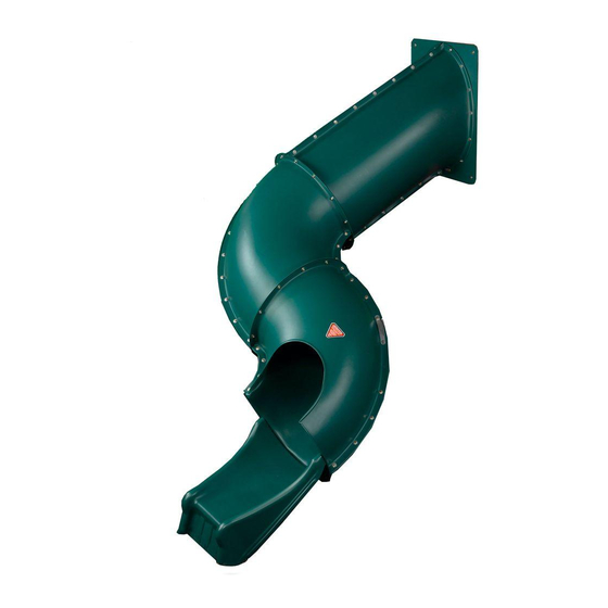
Tunnel Twister
TM
Slide
72'' Minimum
Safety Zone
NOTE:
The Tunnel Twister Slide is Designed to Fit on a
Five Foot Deck Only.
check out http://www.swing-n-slide.com
for updates to these instructions.
ASSEMBLY INSTRUCTIONS
Swing•N•Slide • 1212 Barberry Drive • Janesville, Wisconsin 53545
Visit our web site at: www.swing-n-slide.com or call us at 1-800-888-1232
Advertisement

Related Manuals for Swing-N-Slide Tunnel Twister


Summary of Contents for Swing-N-Slide Tunnel Twister
- Page 1 Tunnel Twister Slide 72'' Minimum Safety Zone NOTE: The Tunnel Twister Slide is Designed to Fit on a Five Foot Deck Only. check out http://www.swing-n-slide.com for updates to these instructions. ASSEMBLY INSTRUCTIONS Swing•N•Slide • 1212 Barberry Drive • Janesville, Wisconsin 53545...
-
Page 2: Hardware Included
ASSEMBLY INSTRUCTIONS TOOLS REQUIRE ELECTRIC DRILL CIRCULAR SAW 1/2" SOCKET & WRENCH TAPE MEASURE SAFETY GLASSES SQUARE HAMMER PHILLIPS BIT & DUST MASK ADDITIONAL LUMBER PURCHASED SEPARATELY Qty. Description 2'' x 4'' x 8’ 2'' x 4'' x 10' 4'' x 4'' x 8’ HARDWARE INCLUDED (2) 1-1/4"... -
Page 3: Slide Components
Tunnel Twister ssembly Instructions SLIDE COMPONENTS (1) Slide Bracket (1) Support Bracket (1) Entrance Panel (1) Entrance Section marked no. 1 (1) Entrance Section marked no.2 (1) Exit Section marked no. 5 (1) 90˚ Sections w/flange, marked no. 4 Top (1) Slide Base marked no. - Page 4 Tunnel Twister ssembly Instructions Fig. 1 A. ENTRANCE SECTION, 90° SECTION AND EXIT SECTION NOTES: • At least two individuals are needed to assemble the Tunnel Twister Slide. • To aid in aligning holes when assembling sections, insert a screwdriver through adjacent holes to maintain hole alignment.
- Page 5 Tunnel Twister ssembly Instructions Fig. 2 Fig. 2a 28'' 2-1/2'' screws per board 2-1/2'' screw Fig. 2b B. Slide Barrier Cont. Note: The recommended opening for this slide is 22-1/4'' Wide x 28'' High. The wood around the Slide Opening must be a minimum of 3’’...
- Page 6 Tunnel Twister ssembly Instructions Fig. 3 Fig. 3a C. Slide Support and Entry 1. Align the mounting panel to the previously assembled entrance section (Fig. 3). Attach the mounting panel to the entrance section at the hole locations indicated in (Fig. 3a) using one 1" bolt, two washers and one loc nut per hole as indicated in (Fig.
- Page 7 Tunnel Twister ssembly Instructions Fig. 4 1-1/2'' 2-1/2'' 2-1/2'' Lag Bolt Lag Bolt Lag Bolt 1-1/2'' 1-1/2'' Lag Bolt Lag Bolt Fig. 4a 2-1/2'' 2-1/2'' 1-1/2'' Lag Bolt Lag Bolt Lag Bolt 1-1/2'' Lag Bolt 2-1/2'' Lag Bolt Section D. Slide Entrance and Elbow 1.
- Page 8 Tunnel Twister ssembly Instructions Fig. 5a Fig. 5 (1) 3/4'' Bolt (2) Flat Washer (1) LocNut (1) 3/4'' Bolt Per Hole (2) Flat Washer (1) LocNut Per Hole Fig. 5b E. Second Elbow and Slide Exit 1. Align the seams of the second Elbow Section to the First Elbow Section as shown in (Fig.
- Page 9 Tunnel Twister ssembly Instructions F. SUPPORT AND BRACKET Fig. 6 FIGURE 13 ASSEMBLY 1. Position the slide bracket as shown in (FIG. 6). Remove appropriate bolts from the slide (the fourth and fifth bolts as indicated), Attach bracket to the underside of the seam using the previously removed hardware (FIG.
- Page 10 Tunnel Twister ssembly Instructions Fig. 7 2'' x 4'' x 18'' 1-1/4'' screws G. Slide Installation. 1. Position slide to determine proper location for stake. 2. Drive wood stake into ground leaving 2'' exposed. 3. Secure the slide bottom to the stake using (2) 1-1/4'' deck screws. (Fig. 7).
- Page 12 Questions???... Call our Customer Service Department at 1-800-888-1232 © PlayCore Inc. 2009 Printed In USA LA 6068...
- Page 13 72 po consulte http://www.swing-n-slide.com/timberbiltplanupdates.htm para ver las actualizaciones de estas instrucciones. Visitez le site http://www.swing-n-slide.com/timberbiltplanupdates.htm pour des mises à jour de ces instructions. Para más información, visite los siguientes sitios: Pour plus d’information, visitez ces liens Internet : http://www.swing-n-slide.com/timberbilt...
- Page 14 Lorsque l’équipement est mis hors service, il doit être démonté et conditionné de sorte qu’aucun danger justifié ne sera présent lors de la mise au rebut de l’ensemble. ¡Importante! Instrucciones de seguridad adicionales para todos los equipos de juego Swing-N-Slide. Guardar esta hoja de instrucciones en caso de que se requiera contactar al fabricante.
- Page 15 INSTRUCCIONES DE ENSAMBLAJE INSTRUCTIONS D’ASSEMBLAGE HERRAMIENTAS REQUERIDAS OUTILS REQUIS SIERRA CIRCULAR TALADRO ELÉCTRICO CINTA MÉTRICA LLAVE Y CUBO DE 1/2" SCIE RONDE PERCEUSE ÉLECTRIQUE RUBAN À MESURER CLÉ ET DOUILLE DE 1/2 po PUNTA DE GAFAS DE SEGURIDAD Y MARTILLO ESCUADRA MÁSCARA ANTIPOLVO DESTORNILLADOR...
- Page 16 Tunnel Twister nstructions d’assemblage de la glissoire Tunnel Twister COMPONENTES DEL TOBOGÁN COMPOSANTES DE LA GLISSOIRE (1) soporte para tobogán (1) soporte de apoyo (1) Support de glissoire (1) Support (1) panel de entrada (1) Panneau d’entrée (1) sección de entrada, marcada con el N.°...
- Page 17 DE SALIDA NOTAS: • Se necesitan por lo menos dos personas para armar el tobogán Tunnel Twister. • Para ayudar a alinear los agujeros al unir las secciones, se debe introducir un destornillador a través de los agujeros adyacentes para mantener la alineación de estos.
- Page 18 Tunnel Twister nstructions d’assemblage de la glissoire Tunnel Twister NOTA: Fig. 2 Este plano muestra la unión del tobogán Tunnel Twister con la estación de juego Palisade. Sin embargo, se debe utilizar este mismo procedimiento para la unión con la estación de juego Summerville.
-
Page 19: Vista Interna
Tunnel Twister nstructions d’assemblage de la glissoire Tunnel Twister Fig. 3 Fig. 3a tornillos de 2-1/2'' por tabla Vis de 2 1/2 po par planche tornillos de 2-1/2'' por tabla Vis de 2 1/2 po par planche... - Page 20 Tunnel Twister nstructions d’assemblage de la glissoire Tunnel Twister Fig. 4 Fig. 4a D. Entrada y soporte del tobogán 1. Alinee el panel de montaje con la sección de entrada ensamblada previamente (Fig. 4). Una el panel de montaje con la sección de entrada en las ubicaciones de...
- Page 21 Tunnel Twister nstructions d’assemblage de la glissoire Tunnel Twister Fig. 5 perno con cabeza cuadrada de 2-1/2'' pernos con cabeza perno con cabeza cuadrada cuadrada de 1-1/2'' tire-fond de 2 1/2 po de 2-1/2'' tire-fonds de 1 1/2 po...
- Page 22 Tunnel Twister nstructions d’assemblage de la glissoire Tunnel Twister Fig. 6a Fig. 6 (1) perno de 3/4'' (2) arandelas planas (1) contratuerca por agujero (1) boulon de 3/4 po (1) perno de 3/4'' (2) rondelles plates (2) arandelas planas (1) contre-écrou par trou...
- Page 23 Tunnel Twister nstructions d’assemblage de la glissoire Tunnel Twister G. ENSAMBLAJE DEL APOYO Y SOPORTE Fig. 7 FIGURE 13 Coloque el soporte para tobogán como se muestra en la (FIG. 7). Retire los pernos correspondientes del tobogán (el cuarto y el quinto, como se indica), una el soporte a la parte inferior de la costura usando los accesorios retirados previamente (FIG.
- Page 24 Fig. 8 Fig. 8 2'' x 4'' x 18" tornillos de 1-1/4'' Vis de 1 1/4 po H. Instalación del tobogán. 1. Ubique el tobogán para determinar la posición correcta de la estaca. 2. Clave la estaca de madera en el suelo y deje 2'' expuestas. 3.
Need help?
Do you have a question about the Tunnel Twister and is the answer not in the manual?
Questions and answers