Advertisement
Loose Parts
Note: Use the chart below to verify that all parts have been shipped.
109-5736
Dealer Pack
Part #
Description
323-6
Cap Screw, Hex 3/8-16 x 1
98-5975
Washer, Belleville
3290-357
Nut, Hex Flange 3/8-16
103-1309
Warranty Registration Form
103-2106
Key, Exmark Ignition
1-603511
Key, Standard Ignition
32128-20
Nut, 5/16-18 Whizlock
109-5733
Literature Pack
Part #
Description
------------
Manual, Operator's
------------
Manual, Parts
109-3498
DVD, Exmark Safety Video
109-6435
Sht, Emissions Warranty
Installing the Rollover Protection
System (Roll Bar)
1. Remove sides and top of crate from the base.
2. Remove roll bar components from the crate.
3. Remove roll bar tubes from sides of crate.
4. Remove the two brackets used to mount the
bottom of the upper roll bar tube to the crate.
5. Remove the 1/2-13 x 3 1/4 capscrews and 1/2-13
hex flange lock nuts from the two brackets at
each end of the upper roll bar tube and retain for
later use (Fig. 1).
6. Remove the (4) 1/4" lag screws holding the wheel
hub brackets to the crate bottom and discard.
FIGURE 1
SETUP INSTRUCTIONS
Qty
Use
8
8
Installing the Rollover Protection System (Roll Bar)
8
1
Fill out and return to Exmark
1
Unit ignition
1
4
For fastening seat tracks to unit seat frame
Qty
Use
1
1
Read and view before operating machine
1
1
7. Raise the rear of the unit approximately 10-12"
and support it with jack stands or equivalent
support.
POTENTIAL HAZARD
♦ Raising the rear of the unit for assembly relying
solely on mechanical or hydraulic jacks could
be dangerous.
WHAT CAN HAPPEN
♦ The mechanical or hydraulic jacks may not be
enough support or may malfunction allowing
the unit to fall, which could cause injury.
HOW TO AVOID THE HAZARD
♦ DO NOT rely solely on mechanical or hydraulic
jacks for support. Use adequate jack stands or
equivalent support.
8. Locate the left and right lower roll bar tubes.
9. Align lower roll bar tubes along rear engine frame
(Fig. 2).
10. LOOSELY install lower roll bar hardware (four
3/8-16 x 1 capscrews, four spring disk washers
and four 3/8-16 whizlock nuts) to the tubes on
each side. (Fig. 2).
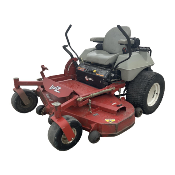
LAZER Z
For Serial Nos. 670,000 and Higher
CAUTION
Page 1 of 5
109-6448 Rev. A
®
AS
Advertisement
Table of Contents

Subscribe to Our Youtube Channel
Related Manuals for Exmark LAZER Z AS


Summary of Contents for Exmark LAZER Z AS
- Page 1 Cap Screw, Hex 3/8-16 x 1 98-5975 Washer, Belleville Installing the Rollover Protection System (Roll Bar) 3290-357 Nut, Hex Flange 3/8-16 103-1309 Warranty Registration Form Fill out and return to Exmark 103-2106 Key, Exmark Ignition Unit ignition 1-603511 Key, Standard Ignition 32128-20 Nut, 5/16-18 Whizlock...
-
Page 2: Installing The Drive Wheels
• Make sure the tab on the lanyard washer is NOTE: Be sure the spring disk washer cone is installed towards the head of the capscrew. installed as shown and points toward the front of the unit. 15. Raise the roll bar into the upright position and secure with the latch pin assemblies on each side. -
Page 3: Servicing The Battery
Servicing the Battery CAUTION WARNING: Battery posts, terminals, and related POTENTIAL HAZARD accessories contain lead compounds, chemicals ♦ If the ignition is in the “ON” position there is known to the State of California to cause cancer and potential for sparks and engagement of reproductive harm. -
Page 4: Installing The Motion Control Levers
Kawasaki 1. Remove air cleaner (with bracket attached) from seat frame. Keep air cleaner and mounting bracket together. 2. Loosely assemble large hose clamp (in dealer lit pack) onto the air cleaner intake hose. 3. Remove the protective tape from the carburetor intake. -
Page 5: Servicing The Engine
Servicing the Engine Refer to Engine Owner’s Manual. Servicing the Hydraulic Oil The machine is shipped with hydraulic oil in the reservoir. 1. Run the machine for approximately 15 minutes to allow any extra air to purge out of the hydraulic system.
Need help?
Do you have a question about the LAZER Z AS and is the answer not in the manual?
Questions and answers