Table of Contents
Advertisement
Quick Links
Advertisement
Table of Contents

Related Manuals for InWin B1


Summary of Contents for InWin B1
- Page 1 User Manual...
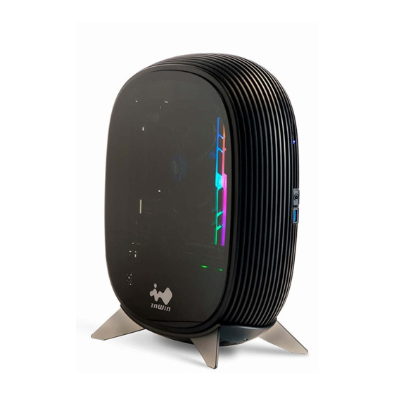
- Page 2 Product Story The B1’s extremely small footprint is perfect for small form factor builds such as HTPCs, light gaming PCs or even a LAN rig. The integrated ventilation in the exquisite streamline design provides a better thermal solution, and you can...
-
Page 3: Specifications
HD Audio (CTIA – SPK/Mic) Internal 2 x 2.5" Drive Bays Thermal Solution Side: 1 x 80 mm (1 InWin Fan Included) Compatibility Power Supply InWin 200W PSU Included Compatibility AC Input/Efficient AC Input: 100 - 240V / 80 PLUS Gold... - Page 4 2.05 x 1.6 x 6.7" Warranty 3 Years Connectors 20+4 Pin Motherboard 8 (4+4) Pin CPU 8 (6+2) Pin PCI-E 4 Pin Peripheral SATA (90 Degree) Floppy * InWin products comply with RoHS regulations. * Specifications may vary based on different regions.
- Page 5 Speed Mode PWM 600-2000 RPM Air Flow 24.09 CFM Air Pressure 1.08mm/ H2O Connector 4-Pin Noise Level 23.55 dB(A) Bearing Type Long Lifespan Sleeve Bearing * InWin products comply with RoHS regulations. * Specifications may vary based on different regions.
-
Page 6: Package Contents
Package Contents 1. B1 Mesh Chassis 2. InWin 200W 80 PLUS Gold PSU 3. InWin 80mm Side fan x 1 4. QR Code Card 5. Accessories Bag... -
Page 7: Accessories Bag
Accessories Bag a. Hexagon Head Screws X 8 b. 2.5” HDD Screws X 10 c. Cable Ties X 5 d. Foot-Stand Stickers X 4... - Page 8 Case Structure 1.SPCC 2. Logo 3. Power Button 4. HDD/Power LED indicator 5. 1 x USB 3.2 Gen 1 6. HD Audio Port (CTIA – SPK/Mic) 7. Removable Foot-stand 8. Release Panel...
- Page 9 Case Structure 1. 2.5” Drive Bay 2. InWin 80mm Side Fan 3. Motherboard Mounting Area 4. InWin 200W 80 PLUS Gold PSU 5. Fan Dust Filter...
-
Page 10: Motherboard Installation
Installation Guide (Please follow the related chapters to assemble) Opening the Chassis Please release the three screws and lift up the top cover (yellow part). Lift it from the two sides (green part). Motherboard Installation Parts Required: Hexagon Head Screws... - Page 11 Connection Cables Switch/LED Connector Black(P_LED) 1 2 Black (HDD) Black(P_LED) 3 4 Black (HDD) Black(P_SW) 5 6 NC Black(P_SW) 7 8 NC Key 9 10 NC HD Audio Header USB 3.2 Header...
- Page 12 Power...
- Page 13 2.5” Drive Bays Installation Parts Required: 2.5” HDD Screws i. Release the two screws and remove the bottom cover. ii. Install the 2.5’’ HDD screws on your SSD screw holes. iii. Attach the SDD in the designated area and push towards the SATA direction.
- Page 14 How to Uninstall the 2.5” Drive Bays i. Push the panel ii. Pull towards the direction to release it.
- Page 15 Foot-Stand Stickers Installation (Optional) Note: After installed, the stickers will be hard to remove. Please use wisely, we suggest using the chassis on vertical position for a better look. Parts Required: Foot-stand Stickers i. Release the two screws and remove the bottom cover. ii.
-
Page 16: Completing Installation
Completing Installation *For more installation instructions, please scan the QR Code or watch the video in the website link: https://youtu.be/cHm2nA2liQY... - Page 17 Please only use your fan in the computer case. Warranty ■ * For more detailed warranty information, please visit the InWin retail website at www.in-win.com. * The actual product is subject to change without prior notice. In Win Development Inc. reserves the right to make final modifications.
- Page 18 Copyright © 2022 In Win Development Inc. All Rights Reserved.
Need help?
Do you have a question about the B1 and is the answer not in the manual?
Questions and answers