Sign In
Upload
Manuals
Brands
Carrier Manuals
Chiller
AquaSnap 61WG Series
Carrier AquaSnap 61WG Series Manuals
Manuals and User Guides for Carrier AquaSnap 61WG Series. We have
2
Carrier AquaSnap 61WG Series manuals available for free PDF download: Installation, Operation And Maintenance Instructions, Operation Instructions Manual
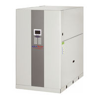
Carrier AquaSnap 61WG Series Installation, Operation And Maintenance Instructions (72 pages)
Water-Cooled/Condenserless Liquid Chillers/Water-Sourced Heat Pumps with or without Integrated Hydraulic Module
Brand:
Carrier
| Category:
Chiller
| Size: 9.25 MB
Table of Contents
Table of Contents
2
1 Introduction
5
Installation Safety Considerations
5
Equipment and Components under Pressure
6
Maintenance Safety Considerations
6
Repair Safety Considerations
7
Measures, Provisions, Procedures against Emergencies
8
2 Preliminary Checks
9
Check Equipment Received
9
Moving and Placing the Unit
9
3 Dimensions, Clearances
11
61WG/30WG 020-045 - Standard Unit
11
61WG/30WG 020-045 - Unit with Top Connections (Option 274)
11
61WG/30WG 020-045 - Unit with Evaporator Hydraulic Module (Option 116)
12
61WG/30WG 020-045 - Unit with Condenser Hydraulic Module (Option 270)
12
61WG/30WG 020-045 - Unit with Evaporator/Condenser Hydraulic Modules (Options 116 + 270)
13
61WG/30WG 020-045 - Stackable Unit (Option 273)
14
61WG/30WG 050-090 - Standard Unit
14
61WG/30WG 050-090 - Unit with Top Connections (Option 274)
15
61WG/30WG 050-090 - Unit with Evaporator Hydraulic Module (Option 116)
15
61WG/30WG 050-090 - Unit with Condenser Hydraulic Module (Option 270)
16
61WG/30WG 050-090 - Unit with Evaporator/Condenser Hydraulic Modules (Options 116 + 270)
16
61WG/30WG 050-090 - Unit with Hydraulic Module and Top Connections (Options 116 + 274 or 270 + 274 or 116 + 270 + 274)
17
61WG/30WG 050-090 - Stackable Unit (Option 273)
17
30WG 110-140 - Standard Unit
18
30WG 110-140 - Unit with Top Connections (Option 274)
18
30WG 110-140 - Unit with Hydraulic Module (Option 116-270)
19
30WG 110-140 - Unit with Hydraulic Module and Top Connections (Option 116-270 and 274)
19
30WG 150-190 - Standard Unit
20
30WG 150-190 - Unit with Top Connections (Option 274)
20
30WG 150-190 - Unit with Hydraulic Module (Option 116-270)
21
30WG 150-190 - Unit with Hydraulic Module and Top Connections (Option 116-270 and 274)
21
30WGA 020-045 - Standard Unit
22
30WGA 020-045 - Unit with Evaporator Hydraulic Module (Option 116)
22
30WGA 020-045 - Stackable Unit (Option 273)
23
30WGA 050-090 - Standard Unit
23
30WGA 050-090 - Unit with Evaporator Hydraulic Module (Option 116)
24
30WGA 050-090 - Stackable Unit (Option 273)
24
30WGA 110-140 - Standard Unit
25
30WGA 110-140 - Unit with Hydraulic Module (Option 116)
25
30WGA 150-190 - Standard Unit
26
30WGA 150-190 - Unit with Hydraulic Module (Option 116)
26
4 Physical and Electrical Data 61Wg/30Wg/30Wga
27
Physical Data 61WG/30WG
27
Physical Data 61WG/30WG/WGA Units with Hydraulic Module
29
Electrical Data 30WG/WGA
29
Short-Circuit Stability Current (TN System (1) ) - Standard Unit (with Main Disconnect Switch)
31
Electrical Data, Optional Hydraulic Module
32
Compressor Usage and Electrical Data Table
36
5 Application Data
38
Operating Limits 61WG/30WG/WGA
38
Operating Range 61WG/30WG/30WGA
39
Minimum Chilled Water Flow
39
Maximum Chilled Water Flow
39
Variable Flow
39
Water Flow Rates
39
Minimum Water Volume
40
Maximum Water Loop Volume (Evaporator and Condenser Side)
40
Expansion Tank
40
Protection against Cavitation (Option 116)
40
Plate Heat Exchanger Pressure Drop (Includes Internal Piping)
41
6 Electrical Connection
42
Electrical Connections, Control Box
42
Power Supply
42
Voltage Phase Imbalance (%)
42
Recommended Wire Sections
42
24 V User Power Reserve
43
30 Wga Unit Connections
44
Recommendations for the Installation of Liquid Chillers with Remote Condenser
44
Piping Installation and Connection
44
8 Pipe Sizing with Refrigerant for 30Wga Units
45
General Considerations and Pipe Size Limits
45
Pipe Sizing
45
Discharge Pipe Sizing
45
9 Water Connections
47
Operating Precautions
47
Frost Protection
48
Flow Switch (Units Without Hydraulic Module)
48
10 Nominal Water Flow Control with Fixed-Speed Pump
49
General
49
Water Flow Control Procedure
49
11 Nominal Water Flow Control with Variable-Speed Pump
51
Pump Flow/Pressure Curve
51
Available External Static Pressure
51
Available External Static Pressure (Variable Speed / Fixed-Speed High-Pressure Single Pumps, Units with Hydraulic Module)
52
Available External Static Pressure
53
12 Operation of 30Wg Units with Specific Heating Control (Option 153)
54
Operating Principle
54
Auxiliary Electronic Board (AUX1) - Analogue and Digital Inputs and Outputs
54
13 Operation of 30Wg Units with the Heating System Manager (Hsm)
55
30 Wg/61Wg Unit Operation with a Drycooler (Option 154)
56
Operating Principle
56
Communication to Control the Drycooler
56
Configuration of the Number of Fan Stages and the Automatic Changeover of the Fan Stages
56
Fan Stage Assignment
56
Units Without Evaporator and Condenser Pump, Three-Way Valve Configuration for Low Outside Temperature Application
56
Drycooler Installation on Units
56
30 Wga Unit Operation with a Remote Air-Cooled Condenser (Option 154)
57
Operating Principle
57
Lead Fan
57
Communication to Control the Remote Condenser
57
Configuration of the Number of Fan Stages and Fan Type Based on the Air-Cooled Condenser Model Used in the Installation
57
16 Unit Operation with a Free Cooling Drycooler
58
Operating Principle
58
Communication to Control the Drycooler
58
Configuration of the Fans Control
58
Water Valves
58
System Installations Recommandation
58
17 Start-Up
59
Preliminary Checks
59
Actual Start-Up
59
Operation of Two Units in Master/Slave Mode (Option 58)
59
Parallel or Serial Connection of Two Units
59
18 Major System Components and Operation Data
60
Compressors
60
Lubricant
60
Evaporators and Water-Cooled Condensers
60
Electronic Expansion Valve (EXV)
60
Refrigerant
60
High-Pressure Switch and High-Pressure Sensor
61
High and Low-Pressure Side Relief Valve
61
Moisture Indicator
61
Filter Drier in the Refrigerant Circuit
61
Fixed-Speed Pump
61
Variable-Speed Pump
61
Evaporator and Condenser Pump Suction Filter
61
Outside Air Temperature (Option 312)
61
19 Options and Accessories
62
20 Maintenance
65
Soldering and Welding
65
General System Maintenance
65
Refrigerant Undercharge
66
Refrigerant Guidelines
66
Leak Detection
66
Evacuation
66
Recharging Liquid Refrigerant
66
Characteristics of R-410A
67
Electrical Maintenance
67
Tightening Torques for the Main Electrical Connections
67
Tightening Torques for the Main Bolts and Screws
67
Compressors
68
Evaporator and Condenser Maintenance
68
Corrosion Check
68
21 Aquasnap Maintenance Program
69
Maintenance Schedule
69
Description of the Maintenance Operations
69
22 Start-Up Ckecklist for Units (Use for Job File)
70
Advertisement
Carrier AquaSnap 61WG Series Operation Instructions Manual (36 pages)
Touch Pilot Junior Control
Brand:
Carrier
| Category:
Control Unit
| Size: 0.7 MB
Table of Contents
Table of Contents
2
1 Safety Considerations
5
General Description
5
Safety Precautions
5
2 Controller Overview
5
Control System
5
System Functionalities
5
Touch Pilot Junior Components
5
Operating Modes
5
3 Hardware Description
6
Control Boards
6
Power Supply to Boards
6
Light Emitting Diodes on Boards
6
Pressure Transducers
6
Temperature Sensors
6
Actuators
7
Available Connections
7
4 Touch Pilot Control Interface
8
User Interface
8
Connections
8
Synoptic Screen
8
Menu Structure (Basic / User Access)
9
Buttons
10
5 Setting up Touch Pilot Junior Control
11
Reading the Welcome Screen
11
Exploring the Synoptic Screen
11
Starting / Stopping the Unit
11
Setting the Schedule
12
Display Settings
13
Main Menu
13
Configuration Menu
14
Override Screen
14
6 Web Connection
14
Web Interface
14
Opening the Web Interface
14
Web Browser Settings
14
7 Touch Pilot Junior Interface - Detailed Menu Structure
15
Main Menu
15
Configuration Menu
21
Alarms Menu
24
8 Touch Pilot Junior Control Operation
25
Start / Stop Control
25
Cooling / Heating
25
Control Interlock Contact
26
Heat Exchanger Water Pump Control
26
Control Point
26
Capacity Control
27
Demand Limit
28
Night Mode
28
Dry Cooler Free Cooling
28
Additional Space Heating Control
28
Built-In DHW and Space Heating Control (HDC)
29
Condensing Pressure Control (Optional)
30
Master / Slave Control
30
9 Diagnostics
31
Control Diagnostics
31
Displaying Current Alarms
31
Resetting Alarms
31
E-Mail Notifications
31
Alarms Description
32
10 Maintenance
35
Advertisement
Related Products
Carrier 61AF
Carrier 60GTN
Carrier 60GTR
Carrier AquaSnap 30MPW Series
Carrier AquaSnap 30WG Series
Carrier AquaSnap 30WGA Series
Carrier AQUASNAP 30RBM Series
Carrier AQUASNAP 30RBP Series
Carrier AQUASNAP 30RA B Series
Carrier 61WG 020
Carrier Categories
Air Conditioner
Heat Pump
Furnace
Thermostat
Chiller
More Carrier Manuals
Login
Sign In
OR
Sign in with Facebook
Sign in with Google
Upload manual
Upload from disk
Upload from URL