Table of Contents
Advertisement
Quick Links
Advertisement
Table of Contents

Related Manuals for laguna PX12


Summary of Contents for laguna PX12
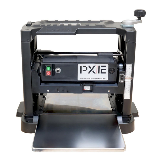
- Page 1 OWNERS’S MANUAL PX12 Planer Quadtec: I Cutterhead Lagunatools.com...
-
Page 2: Warranty
Machines sold through dealers must be registered with Laguna Tools within 30 days of purchase to be covered by this warranty. Laguna Tools guarantees all new machine sold to be free of manufacturers’ defective workmanship, parts and materials. -
Page 3: Table Of Contents
CONTENTS Warranty: Safety: Important Safety Instructions General Safety Rules Unpacking: Inventory Assembly: Components: Power Supply: Connecting Power Operation: Tips Maintenance/Adjustment: Trouble Shooting: Exploded Views: Wiring Diagram Parts List: Specifications: Supplies:... -
Page 4: Safety
SAFETY READ AND UNDERSTAND THIS MANUAL AND ALL INSTRUCTIONS BEFORE USING THIS EQUIPMENT. Failure to follow all instructions may result in electric shock, fire and/or serious personal injury or property damage! Electronic copies of this manual are available www.lagunatools.com SAFETY GUIDELINES - DEFINITIONS This manual contains information that is important for you to know and understand. -
Page 5: Important Safety Instructions
Woodworking, metalworking, composites, etc. (and similar materials) can be dangerous if safe and proper operating procedures are not followed. As with all machinery, there are certain hazards involved with the operation of the machine. Using the machine with respect and caution will considerably lessen the possibility of personal injury. However, if normal safety precautions are overlooked or ignored, personal injury to the operator may result. - Page 6 4. Do not use this machine for other than its intended use. If used for other purposes, LAGUNA TOOLS INC., disclaims any real or implied warranty and holds itself harmless from any injury that may result from that use.
- Page 7 • Lead from lead based paint. • Crystalline silica from bricks, cement and other masonry products. • Arsenic and chromium from chemically treated lumber. Your risk of exposure varies, depending on how often you do this type of work. To reduce your exposure to these chemicals, work in a well- ventilated area and work with approved safety equipment, such as face or dust masks/respirators that are specifically designed to filter out microscopic particles.
- Page 8 20.Make your workshop child proof with padlocks, master switches or by removing starter keys. 21.Give your work undivided attention. Looking around, carrying on a conversation and “horse-play” are careless acts that can result in serious injury. 22.Maintain a balanced stance at all times so that you do not fall or lean against the dust collector.
-
Page 9: General Safety Rules
ADDITIONAL SAFETY INFORMATION Intended use. This machine is intended for the applications discussed and approved by Laguna/SuperMax. Do not use this machine for non-approved applications or flammable, combustible, or hazardous materials. Hazardous dust. Dust created while using machinery may cause cancer, birth defects, or long-term respiratory damage. - Page 10 Wear respirator. Fine dust that is too small to be caught in the filter may be introduced into the ambient air during operation. Always wear a NIOSH- approved respirator during operation and for a short time after to reduce your risk of permanent respiratory damage.
- Page 11 Confirm electrical configuration (Voltage & Phase) of this machine before connecting to power source! GROUNDING INSTRUCTIONS THIS MACHINE MUST BE GROUNDED WHILE IN USE TO PROTECT THE OPERATOR FROM ELECTRIC SHOCK. 1. This machine must be connected to a grounded metal, permanent wiring system;...
-
Page 12: Unpacking
PROPERLY GROUNDED. IF YOU ARE NOT SURE, HAVE A QUALIFIED ELECTRICIAN CHECK THE RECEPTACLE OR DISCONNECT. UNPACKING Your PX12 comes packed in a single box and possibly in a crate, before attempting to assemble this machine, follow these directions: 1. Remove the crate covering the machine, if so packed. -
Page 13: Inventory
I n v e n t o r y Crate: 1 PX12 Planer Box: 1 Dust Chute 3 Screws, Dust Chute 1 T25 Torx Wrench Height Adjustment Handle 1 Screw for Handle Figure 2: Crate with top and front removed & box Report any missing or damaged parts to your dealer or distributor. - Page 14 Machine Preparation and Setup: 1. Install Thickness Adjustment Handle. Place handle on exposed stud, aligning flat of handle with flat of stud, insert mounting screw and tighten. igure 3: Installing Thickness Adjustment Handle The Carriage Lock must be “UP” (unlocked) when turning the Thickness Adjustment Handle (Fig.
- Page 15 The Carriage Lock must be locked when operating the planer! 2. Clean all rust protected surfaces with a commercial de-greaser. DO NOT use acetone, gasoline, lacquer thinner or any type of cleaner that could damage paint. Coat cleaned surfaces with WD-40® or 20W machine oil.
-
Page 16: Components
COMPONENTS Thickness Gauge Carriage Lock Thickness Adjustment Handle Control Panel (See Next Figure) Stock Removal Gauge Thickness Scale Depth Stop Table Extension (2) Lifting Handle (2) Table Figure 5: Main Components Control Panel Overload Reset ON/OFF Switch Figure 6: Control Panel - ON/OFF Switch;... -
Page 17: Power Supply
POWER SUPPLY Power Supply Circuit Requirements The power source circuit for your machine must be g r o u n d e d and r a t e d f o r the a m p e r a g e given below. Never replace a circuit breaker on an existing circuit with one of higher amperage without consulting a qualified electrician to ensure compliance with wiring codes. - Page 18 Calibrating the Thickness Scale Thickness Scale Adjustment Screws Figure 7: Thickness Scale Calibration NOTE: The following procedures describe the use of a “calibrating board”. It is a piece of hardwood which has been surfaced on one side with a jointer, drum sander or wide belt sander. 1.
- Page 19 NOTE: Drawing pencil marks across the width of the top of the calibrating board in several locations can make it easier to determine when the entire surface has been planned. 7. Measure the thickness of the calibrating board with a caliper. 8.
- Page 20 The Stock Removal Gauge on the front of the planer (Fig. 9) identifies the amount of material being removed while the stock is being fed through the planer. 1/16” is the maximum stock removal rate and may be less depending on the material being processed and the condition of the cutterhead knives.
- Page 21 Extension Tables There are two extension tables, one on the infeed and one on the outfeed side of the planer (Fig. 11). 1. Lower both extension tables. 2. Place a straight edge on the bed of the planer and extend over the extension table.
-
Page 22: Operation
OPERATION Place the planer on a secure and stable surface for operation. Clamp or bolt the planer into position. 1. Lower each extension table to support stock. 2. Establish the proper depth of cut (typically less than 1/16”), using the Thickness Adjustment handle and referencing the Thickness Scale or the Material Removal Scale. -
Page 23: Tips
3. Lock the Carriage Lock after setting the depth of cut! Carriage Lock “UP” Unlocked “DOWN” Locked Figure 13: Carriage Lock 4. Start dust collection. 5. Start planer. 6. Feed stock into planer, maintain control and support of stock until the stock is securely feeding through planer. -
Page 24: Maintenance/Adjustment
MAINTENANCE/ADJUSTMENT Quadtec: I Cutterhead Knife rotation/replacement Figure 14: Cutterhead Knife inserts are dangerously sharp. Use extreme caution when inspecting, removing, or replacing knife inserts. Turn planer OFF and disconnect power before performing any maintenance or adjustments! The knife inserts on the 12” Planer are four-sided. When dull, remove each knife, rotate it 90°... - Page 25 Auto Lock, cutterhead Figure 15: Auto Lock It is advisable to rotate all inserts at the same time to maintain consistent cutting. However, if one or more knife inserts develops a nick, rotate only those inserts that are affected. Each knife insert has an etched reference mark so you can keep track of the rotation.
- Page 26 The chain tension for carriage adjustment was established at the factory. When the chain stretches from normal use it may require tensioning. Excessive play in the thickness adjustment handle indicates a potentially loose chain. 1. Disconnect Power to planer. 2. Lay planer on its front side. 3.
-
Page 27: Troubleshooting
TROUBLESHOOTING Description of Possible Cause Corrective Action Symptoms 1. Replace fuse or reset 1. Fuse blown or circuit circuit breaker breaker tripped 2. Have cord replaced 2. Cord damaged 3. Check connection 3. Not connected to 4. Check voltage Machine will not start power source 5. - Page 28 1. Incorrect setting for 1. Adjust feed system infeed, out-feed 2. Support long rollers, pressure bar boards with Snipe 2. Inadequate support extension rollers of long boards 1. Allow wood to dry Fuzzy Grain 1. Planing wood with properly a high moisture 2.
-
Page 29: Exploded Views
EXPLODED VIEWS Cutterhead & Drivetrain... - Page 30 Table & Lift...
- Page 31 Motor...
-
Page 32: Wiring Diagram
Wiring Diagram PX12 PARTS LIST... -
Page 33: Specifications
Part No. Description Specifications 924830-000 Handle Assy. .1 090354-148 Handle .2 250260-615 Knob .3 250262-615 Knob Cover .4 251421-675 Scale Ring .5 250662-615 6200 .6 360302-901 Handle Shaft 000302-103 Round Head Phillip Screw M4-0.7x10 049103-104 T Type Screw M6-1.0x12 000802-101 Round Head Hex. - Page 34 130088-000 Bearing Block 000303-707 Round Head Phillip Screw M5-0.8x20 660010-000 Dust Proof Plate 170737-902 Right Mounting Plate 000303-104 Round Head Phillip Screw M5-0.8x12 Part No. Description Specifications 340098-000 Feed Roller 280036-901 Spring 016204-000 Chain #410x26P 170736-902 Left Mounting Plate 380257-901 Sprocket 150004-000 Sprocket...
- Page 35 090093-147 Carriage 250141-620 Scale Pointer 000301-101 Round Head Phillip Screw M3-0.5x6 251401-615 Scale Plate 170314-458 Pointer 170313-901 Contact Plate 290012-901 Shoulder Screw Self-Tapping Screw w/Lock 230238-905 Washer 360297-000 001802-102 Cap Screw w/Lock Washer M6-1.0x20/6.5x10.5 030206-001 Ball Bearing 6202 010103-000 Retaining Ring RTW-35 Part No.
- Page 36 251402-000 Right Side Cover 090353-147 Base 001902-101 Nylock Set Screw M6-1.0x10 150005-000 Sprocket 270007-901 Clip 921933-001 Extension Table Assembly 001701-101 Cap Screw w/Washer M8-1.25x20/8x23x2.0 016211-000 Chain #410x82P 001201-501 Tapping Screw M4-1.41x12 360306-902 Lead Screw 251403-000 Left Side Cover 021102-000 Cord Clamps ACC-2.5 910140-000 Motor Assembly...
-
Page 37: Supplies
(635 x 432 x 546 mm) Machine weight: 65 lbs. (30 kg.) Shipping weight: 72 lbs. (33 kg.) SUPPLIES: Replacement knives Replacement knife screws Contact Laguna Tools for supplies : 800.234.1976 www.lagunatools.com LAGUNA TOOLS 744 Refuge Way Suite 200 Grand Prairie TX 75050 800.234.1976... - Page 38 021121...
Need help?
Do you have a question about the PX12 and is the answer not in the manual?
Questions and answers