Table of Contents
Advertisement
Advertisement
Table of Contents

Related Manuals for laguna PX20


Summary of Contents for laguna PX20
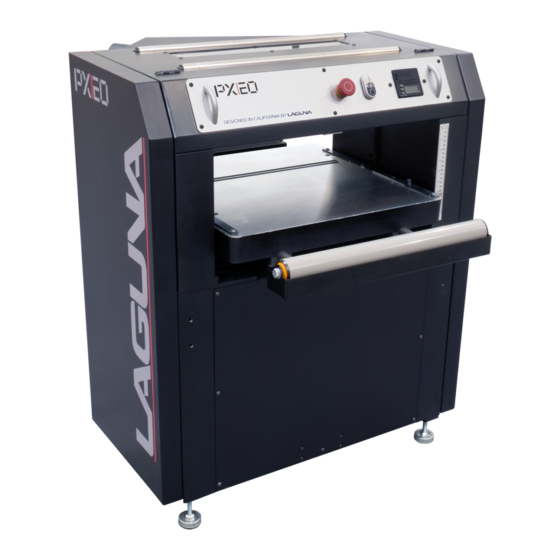
- Page 1 OWNERS’S MANUAL PX20 Planer Lagunatools.com...
- Page 2 Thank you for investing in a PX20 Planer by Laguna Tools. This planer is one of a family of unique machines proudly offered by Laguna Tools. Every Laguna machine is engineered for years of dependable service. Please feel free to contact Laguna Tools if you have a question or suggestion.
-
Page 3: Table Of Contents
CONTENTS Warranty: Safety: Important Safety Instructions General Safety Rules Unpacking: Assembly: Components: Power Supply: Connecting Power Operation: Maintenance/Adjustment: Trouble Shooting: Exploded Views: Wiring Diagram Parts List: Specifications: Supplies:... -
Page 4: Safety
SAFETY READ AND UNDERSTAND THIS MANUAL AND ALL INSTRUCTIONS BEFORE USING THIS EQUIPMENT. Failure to follow all instructions may result in electric shock, fire and/or serious personal injury or property damage! Electronic copies of this manual are available at . www.lagunatools.com SAFETY GUIDELINES - DEFINITIONS This manual contains information that is important for you to know and understand. This information relates to protecting YOUR SAFETY and PREVENTING EQUIPMENT PROBLEMS. To help you recognize this information, we use the symbols below. Please read the manual and pay attention to these sections. -
Page 5: Important Safety Instructions
dangerous, do not try it. Figure out an alternative procedure that is safer. REMEMBER: Your personal safety is your responsibility. IMPORTANT SAFETY INSTRUCTIONS This machine was designed for certain applications only. We strongly recommend that this machine not be modified and/or used for any application other than that for which it was designed. If you have any questions relative to a particular application, DO NOT use the machine until you have first contacted the manufacturer to determine if it can or should be performed on the product. - Page 6 4. Do not use this machine for other than its intended use. If used for other purposes, LAGUNA TOOLS INC., disclaims any real or implied warranty and holds itself harmless from any injury that may result from that use.
- Page 7 14. Keep safety guards in place at all times when the machine is in use. If removed for maintenance purposes, use extreme caution and replace the guards immediately when maintenance is complete. 15. Make sure the dust collector is on a flat even surface and the wheels locked in place before use.
-
Page 8: General Safety Rules
ADDITIONAL SAFETY INFORMATION Intended use. This machine is intended for the applications discussed and approved by Laguna. Do not use this machine for non-approved applications or flammable, combustible, or hazardous materials. Hazardous dust. Dust created while using machinery may cause cancer, birth defects, or long-term respiratory damage. - Page 9 Wear respirator. Fine dust that is too small to be caught in the filter may be introduced into the ambient air during operation. Always wear a NIOSH-approved respirator during operation and for a short time after to reduce your risk of permanent respiratory damage.
- Page 10 GROUNDING INSTRUCTIONS THIS MACHINE MUST BE GROUNDED WHILE IN USE TO PROTECT THE OPERATOR FROM ELECTRIC SHOCK. 1. This machine must be connected to a grounded metal, permanent wiring system; or an equipment-grounding conductor must be run with the circuit conductors and connected to the equipment-grounding terminal or lead on the appliance.
-
Page 11: Unpacking
UNPACKING Your PX20 comes packed in a single box attached to a pallet. Before attempting to assemble this machine, follow these directions: 1. Carefully cut the banding straps and remove them from the box, if so packed. 2. Remove the box covering the machine. -
Page 12: Assembly
I n v e n t o r y Pallet 4 Leveling Feet with nuts (typically installed) Bubble Wrap 1 Dust Chute 4 Hex Head Screws M6x10 2 T25 Torx Wrenches 4 Lifting hooks & hardware Figure 2: Pallet Report any missing or damaged parts to your dealer or distributor. Prior to machine assembly and use, read this manual thoroughly to familiarize yourself with proper assembly, maintenance and safety procedures. - Page 13 Machine Preparation and Setup: 1. Level machine using the four leveling feet on each of the four corners. Lock leveling feet into position with the nut on the leveling foot stud. Figure 3: Leveling Feet 2. Clean all rust protected surfaces with a commercial de-greaser. DO NOT use acetone, gasoline, lacquer thinner or any type of cleaner that could damage paint.
- Page 14 NOTE: Make sure the dust collection system has sufficient capacity and CFM for this planer. Always turn ON the dust collector before planning. Clips, hood (2) Figure 5: Dust Chute & Hood Clips Opening Hood 1. Release the 2 Clips (Fig. 5) on each side of the hood. 2.
-
Page 15: Components
Feed Speed Control Table Extension Roller (2) Table Height Adjustment Leveling Feet (4) Table Figure 6: Main Components of PX20 Control Panel C B Figure 7: Control Panel A. Emergency Stop (E-STOP); stops all functions of machine, however, power continues to machine. NOTE: To reset E-STOP, rotate switch clockwise until the button “pops”... -
Page 16: Power Supply
POWER SUPPLY Power Supply Circuit Requirements The power source circuit for your machine must be g r o u n d e d and r a t e d f o r sufficient a m p e r a g e . Never replace a circuit breaker on an existing circuit with one of higher amperage without consulting a qualified electrician to ensure compliance with wiring codes. - Page 17 Calibrating the Thickness Scale Figure 8: Thickness Scale Adjustment NOTE: The following procedures describe the use of a “calibrating board”. It is a piece of hardwood which has been surfaced on one side with a jointer, drum sander or wide belt sander. 1.
- Page 18 NOTE: Drawing pencil marks across the width of the top of the calibrating board in several locations can make it easier to determine when the entire surface has been planned. 7. Measure the thickness of the calibrating board with a caliper. 8.
- Page 19 DRO Button Reference and Use It is helpful to familiarize these buttons and their purpose with the Wixey™ DRO Figures 10-12: DRO Reference...
-
Page 20: Operation
OPERATION 1. Establish the proper depth of cut (typically less than 1/16” (1.6mm)), using either the DRO or scale. 2. Pull out and lock each extension roller to support long stock 3. Start dust collection. 4. Start planer. 5. Adjust feed speed (Fig. 7, C) to desired speed (16 or 28 FPM), while planer is running. - Page 21 Turn planer OFF and disconnect power before performing any maintenance or adjustments! The knife inserts on the 20” Planer are four-sided. When dull, remove each knife, rotate it 90° for a fresh edge, and re-install it (52-60 in/lb.). No further adjustment is necessary.
- Page 22 Figures 14 and 15 show dimensions in mm for the set up block for general planning needs. Figures 14 & 15: Gauge Block Figure 16: Cutterhead Anti-Kickback Fingers Anti-kickback fingers help prevent stock from being kicked out of the machine towards the user.
- Page 23 Adjustment of Infeed Roller The in-feed roller should be set 0.02” (0.5mm) below the lowest point of knife. Make sure the knives are set properly see the “Setting / Changing Knives” section prior to making any adjustments. 1. Disconnect machine from power source. 2.
- Page 24 Adjustment of Out-feed Roller The out-feed roller should be set 0.02” (0.5mm) below the lowest point of knife. Make sure the knives are set properly see the “Setting / Changing Knives” section prior to making any adjustments. 1. Disconnect machine from power source. 2.
- Page 25 Poly-V-Belt Adjustment Poly-V-belt (Fig. 22, D) tension has been set at the factory. If the belt has stretched and need adjustment. 1. Disconnect machine from power source. 2. Open lower rear, and lower left-hand side panels. Loosen and tighten four adjustment nuts (Fig.
- Page 26 Disconnect the machine from power source before proceeding with any maintenance, lubrication or assembly! Failure to comply may cause serious injury! Periodic, or regular inspections are required to ensure that the machine is in proper adjustment, and that all hardware is tight. Figure 24: Table Roller Adjustment Clean out-feed rollers and table with a non-...
- Page 27 Lubrication (Fig. 25, 26 & 27) No. Position Grease Gear Box Chain Chain Chain Chain Bushing Lead Screw - The Gear Box oil must be changed after 2500 hours of work. (Fig. 25) - All chains must be lubricated regularly. (Fig.
-
Page 28: Troubleshooting
TROUBLESHOOTING Description of Possible Cause Corrective Action Symptoms 1. Replace fuse or reset 1. Fuse blown or circuit circuit breaker breaker tripped 2. Have cord replaced 2. Cord damaged 3. Check connection 3. Not connected to 4. Check voltage Machine will not start power source 5. - Page 29 1. Allow wood to dry Fuzzy Grain 1. Planning wood properly with a high 2. Rotate, replace or moisture content sharpen knives 2. Dull knives 1. Inadequate feed roll 1. Adjust feed roll pressure tension or lower 2. Planer bed dirty feed rollers 3.
-
Page 30: Exploded Views
EXPLODED VIEWS Cutterhead & Drivetrain... - Page 31 Table & Lift...
- Page 32 Stand & Motor...
-
Page 33: Wiring Diagram
Wiring Diagram 400V Three Phase... - Page 34 MPLANPX20-0130 Part List Part No. Descriptions Specification Q'ty 000804-107 Round Head Hex Screw M5*0.8P*12 174833-196 Dust Chute 000302-201 Round Head Phillips Screw M4*0.7P*6 230409-905 Buckle CT-22 174832-196 Top Cover 340007-615 Block 200113-615 Sponge 174723-904 Roller Bracket 030119-000 Ball Bearing 10 361392-906 Roller 11 251317-620 PC Board...
- Page 35 57 012006-001 8*8*40 924839-001 Helical Cutterhead Assy LAGUNA SHEAR-TECⅡ 59 043343-000 Retaining Ring NBR/46.3*3.1 60 000902-102 Hex. Screw W/Washer M6*1.0P*12 61 924838-001 Infeed Roller Assembly 62 270015-901 Spring Plate 63 361389-902 Support Rod 64 000203-104 SET Screw M6*1.0P*12 65 174837-019...
- Page 36 112 360357-901 Shaft 113 012004-003 6*6*40 114 130404-000 Shifting Claw 115 924811-001 Gear Assembly 116 030205-002 Ball Bearing 6201 117 320356-000 Shaft 118 320198-000 Gear 119 012003-002 5*5*10 120 320406-000 Gear 121 012003-003 5*5*12 122 320160-000 Shaft 123 043337-000 O-Ring 124 043401-000 Plug PT1/4”-19...
- Page 37 144 000805-705 Round Head Hex Screw M4*0.7P*8 145 006001-001 Flat Washer 4.3*10*1.0t 146 660289-000 Paking 147 051416-902 Lead Screw Seat 148 012001-003 3*3*10 149 012002-005 4*4*12 150 051415-902 Main Lead Screw Seat 151 660290-000 Packing 152 920133-001 Thrust Bearing 153 000103-107 CAP Screw M6*1.0P*20 154 381404-902...
- Page 38 .5 380148-901 Adjustable Rod .6 008007-100 Hex. Nut M10*1.5P(17B*8H) .7 006003-091 Flat Washer 13*28*3.0t 197 925024-001 Motor Mounting Assembly For MEPS Motor .1 000204-102 SET Screw M8*1.25P*10 .2 010209-000 Retaining Ring ETW-15 .3 361423-902 Support Rod .4 050321-008 Motor Plate .5 380148-901 Adjustable Rod .6 008007-100...
- Page 41 Caster Set Installing universal caster set (Fig. 28): 1. Raise and block planer for attaching caster set. 2. Assemble swivel caster into swivel caster bracket (straight bracket) by placing bolt #5 through bracket and caster and securing with lock nut #4. Then place bolt #6 down through bracket into caster mount.
-
Page 42: Parts List
.4 009102-200 Lock Nut 3/8”-16 (14.2Bx11.5H) 174876-904 Bracket, Swivel Caster 174931-904 Universal Bracket Not used for planer SPECIFICATIONS: PX20 Main Motor: 5 HP / 1750 RPM Electrical: 400V / 50Hz / 3PH 3 Phase Circuit: Air Volume: 600 CFM per port (min.) Inlet: One 4”... -
Page 43: Supplies
SUPPLIES: Replacement knives Replacement knife screws Contact your local distributor : CARBATEC PTY LTD Toll Free: 1800 658 111 www.carbatec.com.au LAGUNA TOOLS 800.234.1976 www.lagunatools.com 744 Refuge Way Suite 200 Grand Prairie TX 75050 012221...
Need help?
Do you have a question about the PX20 and is the answer not in the manual?
Questions and answers