
Subscribe to Our Youtube Channel
Related Manuals for laguna MPLAN2010-0130


Summary of Contents for laguna MPLAN2010-0130
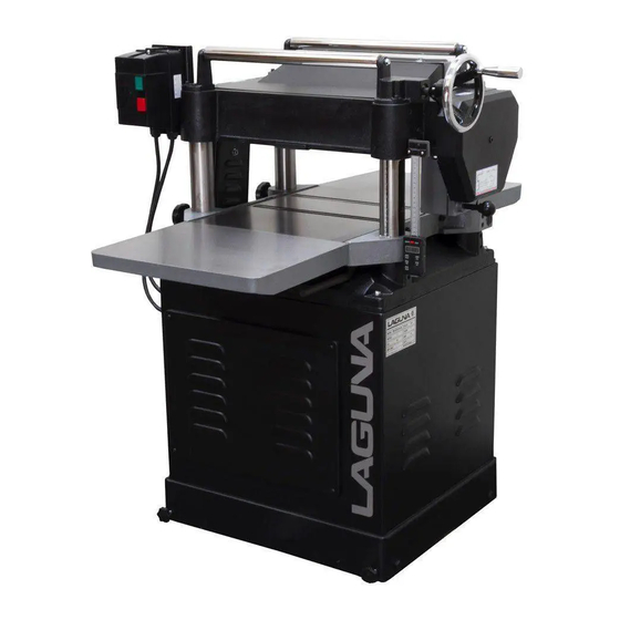
- Page 1 20" Planer With Shear Tech ll MPLAN2010-0130 OPERATING MANUAL 17101 Murphy Avenue. Irvine, California 92614 www.lagunatools.com 800.234.1976...
- Page 2 For Your Own Safety Read Instruction Manual Before Operating This Tool Read this manual completely and observe all warning labels on the machine. This machine has made every attempt to provide a safe, reliable, easy-to-use piece of machinery. Safety, however, is ultimately the responsibility of the individual machine operator.
- Page 3 Your risk from these exposures varies, depending on how often you do this type of work. To reduce your exposure to these chemicals, work in a well-ventilated area, and work with approved safety equipment, such as those dust masks that are specifically designed to filter out microscopic particles. Familiarize yourself with the following safety notices used in this manual: CAUTION: (This means that if precautions are not heeded, it may result in minor or moderate injury and/or possible machine damage)
- Page 4 20” PLANER Thank you for choosing this planer. This unit is carefully tested and inspected before shipment and if properly used and maintained, will provide you with 1 year of reliable service. To ensure optimum performance and trouble free operation a reasonable amount of care and attention is required.
-
Page 5: Dust Chute Assembly
ASSEMBLY EXTENSION TABLE Ask another person provide assistance to hole on the extension table. To lock up screws into the holes (Fig. 4) then place straight edge through machine let it lies across both table and extension table (Fig.5). If they are not aligned, loosen screws and adjust them until they are aligned then tighten all of screws. - Page 6 SHEARTEC 2 CUTTERHEAD Knife inserts are dangerously sharp. Use extreme caution when inspecting, removing, or replacing knife inserts. The knife inserts on the Jointer are four-sided. When dull, simply remove each insert, rotate it 90° for a fresh edge, and re-install it. No further adjustment is necessary.
- Page 7 PARTS LUBRICATION REQUIRED POSITION GREASE OIL WORM GEAR GEAR BOX CHAIN CHAIN CHAIN BRACKET LEAD SCREW COLUMN CLEAN & OIL Fig. 10 Fig. 8 - Worm Gear is used to adjust the table up or down. (Fig. 9) - The oil in Gear Box must be changed after 2500 hours of work.
-
Page 8: Control The Depth Of Cutting
CONTROL THE DEPTH OF CUTTING The cutting depth scale is a combination of inch / metric scale, the cutting range is from 0 to 8" (204 mm). The distance between upward or downward of driving handle is 0.059" (1.5mm) one complete turn. Before adjusting the table upward, or downward;... - Page 9 FEED ROLL SPEED RATE The rate of speed is transmitted by shift gears located in gear box. The shift gear handle (Fig.19) performs with three different methods of speed by using the shift handle to pull or push. Fig.20 Position A: feed roll is functioning on 20-FPM speed rate.
- Page 10 ADJUSTMENT TRANSMITTING ROLLER Verify that roller and table are both at the same height. (Fig.24) ADJUSTING TABLE ROLLER To reduce friction between stock and table, two table roller have been assembled on machine. Adjustments will be needed when planning with the different types of wood.
-
Page 11: Adjusting Spring Tension Of Feed Roller
ASSEMBLING CHAIN If head casting is not parallel to table, tilt planer on it’s side. Remove bolt C and loosen bolt (D) (Fig.27). This will enable you to move the idler sprocket assembly (E) this procedure will release the tension of the chain. Remove chain from sprocket on the end that must be adjusted. - Page 12 ADJUSTING INFEED AND OUTFEED ROLLER Before starting with the adjustment, you must check the position of the cutting head. You will need; 1. Thickness gauge 0.5m/m 2. Home made gauge block - First turn the wheel handle to make table upward. - Use hand to turn cutting head left and right, to make blade contact with the gauge block.
- Page 13 CHECKING OUTFEED ROLLER 1. Place gauge block under outfeed roller. ( Fig.34) 2. Loosen nut no.(3) and screw no.(4), this will allow for the outfeed roller to move upwards, or downwards. 3. Make the roller touch the top of gauge block. 4.
- Page 14 CHECK HEIGHT OF CHIPBREAKER When adjusting the chipbreaker, the correct position of wooden gauge and 0.1m/m thickness gauge must be, as shown in (Fig.37). Adjust process of screw and nut as shown in (Fig. 38). Fig. 37 Adjustments 1. Place wooden gauge and thickness gauge as shown in (Fig.37) 2.
-
Page 15: Digital Readout
DIGITAL READOUT The digital scale equipped with 20” planer can serve many applications, however for wood planning we need only concern ourselves with the ON/OFF, SET, and mm/in buttons. When set properly the digital readout will display the thickness of the finished product. Calibration: In order to calibrate the unit first run a board through the planer and measure the finished thickness with a set of vernier calipers. - Page 20 PARTS LIST FOR MPLAN2010-0130 Part No. Descriptions Q'ty 230118-000 170871-000 BELT GUARD FRONT 014009-000 V-BELT 380147-901 BOLT 000003-204 HEX. SCREW M8*1.25P*20 006001-043 FLAT WASHER 8.2 *30*4.0t 000902-202 HEX SCREW W/WASHER M6*1.0P*12 170432-000 BELT GUARD REAR 009005-200 HEX NUT 5/16"-18NC 050273-901...
- Page 21 Part No. Descriptions Q'ty 170406-901 HOOK 170474-901 SHAFT 000103-110 SOC HD CAP SCREW M6*1.0P*35 170475-904 SIDE COVER GUARD 937574-000 MAGNETIC SWITCH ASSY 5HP.1PH 821007-030 MAGNETIC SWITCH 5HP.1PH 42.1 42.2 172507-904 SWITCH MOUNTING PLATE 003303-207 ROUND HD SCREW 3/16"-24NC*5/8" 42.3 009003-200 HEX NUT 3/16"-24NC 42.4...
- Page 22 Part No. Descriptions Q'ty 360405-000 OUTFEED ROLLER 012003-008 5*5*22 070012-000 CHAIN SPROCKET 006001-020 FLAT WASHER 6.2*20*3.0t 000002-203 HEX. SCREW M6*1.0P*16 070016-025 BRACKET 360386-000 SHAFT 170478-019 CHIP BREAKER 070013-000 CHAIN SPROCKET 010003-000 RETAINING RING STW-12 010209-000 RETAINING RING ETW-15 250160-615 SPACER 172281-905 ANTI-KICK BACK 360387-000...
- Page 23 Part No. Descriptions Q'ty 043608-000 OIL SEAL TC28*40*8 050281-000 GEARBOX 340012-615 GEARBOX GASKET 922351-000 GEAR ASSEMBLY 010102-000 RETAINING RING RTW-32 360357-901 SHAFT 280052-000 SPRING 017002-000 STEEL BALL 043505-000 OIL SEAL SC25*47*6 030306-000 BALL BEARING 6204Z(A) 006001-032 FLAT WASHER 6.6*13*1.0t 070014-000 SHIFTING CLAW 360358-901 SHAFT...
- Page 24 Part No. Descriptions Q'ty 138.3 000003-204 HEX. SCREW M8*1.25P*20 138.4 050351-902 MOTOR PULLEY 138.5 006001-043 FLAT WASHER 8.2*30*4.0t 138.6 021203-000 RELIEF BUSHING SW-P6H 138.7 021369-000 RELIEF BUSHING PGA13.5-11B 008009-100 HEX NUT M12*1.75P 000003-208 HEX. SCREW M8*1.25P*40 021801-000 RELIEF BUSHING NB-1722 021369-000 RELIEF BUSHING PGA13.5-11B...
- Page 25 Part No. Descriptions Q'ty 012002-004 4*4*10 360397-000 ELEVATING SCREW 040003-000 HEX. WRENCH 040004-000 HEX. WRENCH 040005-000 HEX. WRENCH 040006-000 HEX. WRENCH 040201-000 WRENCH BOX 8*10 040204-000 WRENCH BOX 12*14 040206-000 WRENCH BOX 17*19 050299-000 ROLLER BRACKET 360398-902 ROLLER 050300-000 ELEVATING SCREW GEARBOX 000103-113 SOC HD CAP SCREW M6*1.0P*50...
- Page 26 Part No. Descriptions Q'ty 000303-105 ROUND HD SCREW M5*0.8P*15 380168-901 WASHER 490124-000 TERMNAL COVER 003303-102 ROUND HD SCREW 3/16"-24NC*1/4" 000303-103 ROUND HD SCREW M5*0.8P*10 006502-100 TOOTH WASHER 5.3*10...
Need help?
Do you have a question about the MPLAN2010-0130 and is the answer not in the manual?
Questions and answers