Table of Contents
Advertisement
Quick Links
Advertisement
Table of Contents

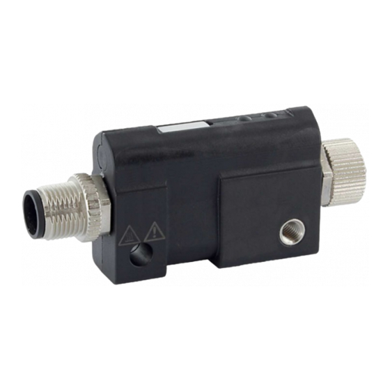
Summary of Contents for Pepperl+Fuchs ICA-AI-I/U-IO-V1
- Page 1 ICA-A*-I/U-IO IO-Link analog converter Manual...
- Page 2 Phone: +49 621 776 - 0 E-mail: info@de.pepperl-fuchs.com North American Headquarters Pepperl+Fuchs Inc. 1600 Enterprise Parkway Twinsburg, Ohio 44087 Phone: +1 330 425-3555 E-mail: sales@us.pepperl-fuchs.com Asia Headquarters Pepperl+Fuchs Pte. Ltd. P+F Building 18 Ayer Rajah Crescent Singapore 139942 Phone: +65 6779-9091 E-mail: sales@sg.pepperl-fuchs.com https://www.pepperl-fuchs.com...
-
Page 3: Table Of Contents
ICA-A*-I/U-IO Contents Introduction........................ 4 Content of this Document ................4 Target Group, Personnel ................4 Symbols Used ....................5 General Safety Notice..................6 Product Description ....................7 Intended Use ....................7 Versions ......................7 Dimensions..................... 7 LED Indicators ....................8 2.4.1 LED 1.......................... -
Page 4: Introduction
ICA-A*-I/U-IO Introduction Introduction Content of this Document This document contains information required to use the product in the relevant phases of the product life cycle. This may include information on the following: • Product identification • Delivery, transport, and storage •... -
Page 5: Symbols Used
ICA-A*-I/U-IO Introduction Symbols Used This document contains symbols for the identification of warning messages and of informative messages. Warning Messages You will find warning messages, whenever dangers may arise from your actions. It is mandatory that you observe these warning messages for your personal safety and in order to avoid prop- erty damage. -
Page 6: General Safety Notice
ICA-A*-I/U-IO Introduction General Safety Notice Danger! Death or serious injury due to electric shock. High electrical voltage in the machine/plant. When working on the device, observe the five safety rules of electrical engineering. According to DIN VDE 0105-100—Operation of electrical installations—Part 100: General requirements Protect people and devices from high electrical voltage: •... -
Page 7: Product Description
Take appropriate measures to prevent radio interference. Versions The manual applies to the following variants. Analog input (I/U) to IO-Link converter Model number Model code 70128166 ICA-AI-I/U-IO-V1 IO-Link to analog output converter (I/U) Model number Model code 70128167 ICA-AO-I/U-IO-V1 Dimensions 77.2... -
Page 8: Led Indicators
ICA-A*-I/U-IO Product Description LED Indicators The device has 2 LEDs for the status indicator. LED 2 LED 1 Figure 2.2 LED 1: Device status / diagnostics LED 2: IO-Link status 2.4.1 LED 1 LED 1 displays device and function status information. Green indicates the general device sta- tus. -
Page 9: Led 2
ICA-A*-I/U-IO Product Description ICA-AI* variant configured as current input Status Description Red flashing (1 Hz) Input current outside the nominal measuring range / outside the parameterizable range Red flashing (2 Hz) Sensor supply overcurrent Red off Table 2.3 ICA-AO* variant configured as voltage output Status Description Red flashing (1 Hz) -
Page 10: Interfaces And Connections
ICA-A*-I/U-IO Product Description Interfaces and Connections Plug assignment ICA-AI-I/U-IO-V1 Connection for Connector Plug type/assignment IO-Link M12, 4-pin, plug, A-coded 1: +24 V (L+) 2: n.c. 3: GND (L-) 4: C/Q Analog input M12, 4-pin, socket, A-coded 1: +24 V (L+) - Page 11 ICA-A*-I/U-IO Product Description Sensors with voltage output (-10/0 V ... +10 V) Figure 2.4 ICA-AI-I/U-IO-V1 +24 V (L+) AI (voltage) GND (L-) n.c. Analog outputs Actuators with analog input can be used depending on the adapter type. Actuators with current input (0/4 mA ... 20 mA) Figure 2.5...
-
Page 12: Accessories
ICA-A*-I/U-IO Product Description Actuators with voltage input (-10/0 V ... +10 V) Figure 2.6 ICA-AO-I/U-IO-V1 +24 V (L+) n.c. GND (L-) AO (voltage) IO-Link interface All IO-Link masters that support IO-Link standard 1.12 or 1.0 can be used. Sensors with current output (0/4 mA ... 20 mA) IO-Link-Masterport IO-Link-Slaveport Figure 2.7... -
Page 13: Installation
ICA-A*-I/U-IO Installation Installation Preparing for Mounting Danger! Death or serious injury due to electric shock. High electrical voltage in the machine/plant. • When working on the device, observe the five safety rules of electrical engineering. • Only connect supplies that provide protection against electric shock according to SELV or PELV. -
Page 14: Connection
ICA-A*-I/U-IO Installation Connection Caution! Property damage due to unsuitable fastening screws! The use of unsuitable fastening screws can cause property damage. • Use fastening screws that are appropriate for the type of mounting surface. Figure 3.2 IO-Link Connection Name plate, replaceable LED 1: Device status / diagnostics LED 2: IO-Link status Analog input/output... -
Page 15: Operation
ICA-A*-I/U-IO Operation Operation IO-Link Parameters Note All details of the IO-Link parameters can be found in the IO device description for the device on our website www.pepperl-fuchs.com. -
Page 16: Maintenance
ICA-A*-I/U-IO Maintenance Maintenance Servicing The device bus nodes and modules are maintenance-free. No inspection and maintenance intervals are required for ongoing operation. Replace defective bus nodes and/or defective modules. -
Page 17: Glossary And List Of Abbreviations
ICA-A*-I/U-IO Glossary and List of Abbreviations Glossary and List of Abbreviations Abbreviation/ designation Meaning Analog input Analog output Binary digit Byte 1 byte equals 8 bits Diagnostic coverage / degree of detection of errors Deutsches Institut für Normung (German Institute for Standardiza- tion) Electromagnetic compatibility European standard... - Page 18 Pepperl+Fuchs Quality Download our latest policy here: www.pepperl-fuchs.com/quality www.pepperl-fuchs.com © Pepperl+Fuchs · Subject to modifications Printed in Germany / DOCT-6995B...


Need help?
Do you have a question about the ICA-AI-I/U-IO-V1 and is the answer not in the manual?
Questions and answers