
Subscribe to Our Youtube Channel
Related Manuals for Panametrics DigitalFlow XGS868i


Summary of Contents for Panametrics DigitalFlow XGS868i
- Page 1 Flow DigitalFlow™ XGS868i Panametrics Steam Ultrasonic Mass Flow Transmitter (1 & 2 Channel) Startup Guide 910-196U Rev. G panametrics.com Jul 2021...
- Page 3 Flow DigitalFlow™ XGS868i Panametrics Steam Ultrasonic Mass Flow Transmitter (1 & 2 Channel) Startup Guide 910-196U Rev. G Jul 2021 panametrics.com Copyright 2021 Baker Hughes company. This material contains one or more registered trademarks of Baker Hughes Company and its subsidiaries in one or more countries.
- Page 4 [no content intended for this page]...
- Page 5 Preface Information Paragraphs Note: These paragraphs provide information that provides a deeper understanding of the situation, but is not essential to the proper completion of the instructions. IMPORTANT: These paragraphs provide information that emphasizes instructions that are essential to proper setup of the equipment.
- Page 6 Environmental Compliance Waste Electrical and Electronic Equipment (WEEE) Directive Panametrics is an active participant in Europe’s Waste Electrical and Electronic Equipment (WEEE) take-back initiative, directive 2012/19/EU. The equipment that you bought has required the extraction and use of natural resources for its production. It may contain hazardous substances that could impact health and the environment.
-
Page 7: Table Of Contents
Contents Chapter 1. Installation Introduction ..................... .1 Unpacking . - Page 8 Contents Electrical Specifications..................53 4.2.1 Power Supply.
-
Page 9: Chapter 1. Installation
To ensure safe and reliable operation of the Model XGS868i Ultrasonic Flow Transmitter, the system must be installed in accordance with the guidelines established by Panametrics engineers. Those guidelines, which are explained in detail in this chapter, include the following specific topics: •... -
Page 10: Site Considerations
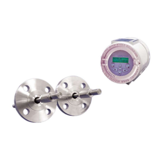
Chapter 1. Installation Site Considerations Because the relative location of the flowcell and the electronics enclosure is important, use the guidelines in this section to plan the XGS868i installation. Figure 1 shows a typical XGS868i enclosure and spoolpiece ready for insertion into a process line. -
Page 11: Flowcell Location
Note: When using non-Panametrics cables to connect the flow rate transducers to the Model XGS868i electronics enclosure, the cables must have electrical characteristics identical to the Panametrics cables. Type RG62 a/u coaxial cable should be used, and each cable must be the same length (within ±4 in.). -
Page 12: Installing A Flowcell
Figure 1 on page 2 shows a typical Model XGS868i spoolpiece, with a mounting bracket to hold the electronics enclosure. For detailed instructions on installing the transducers and/or spoolpiece, refer to the supplied drawings and the enclosed Panametrics Gas Transducer Installation Guide (916-049). Installing Temperature and Pressure Transmitters Optional temperature and pressure transmitters may be installed near the ultrasonic transducer ports as part of the flowcell. -
Page 13: Mounting The Xgs868I Electronics Enclosure
Chapter 1. Installation Mounting the XGS868i Electronics Enclosure The standard Model XGS868i electronics package is housed in a Type-4X weather-resistant enclosure suitable for indoor or outdoor use. Refer to Figure 8 on page 21 for the mounting dimensions and the weight of this enclosure. The Model XGS868i electronics enclosure is fitted with a mounting boss that has a single 3/4”... - Page 14 Chapter 1. Installation Making the Electrical Connections (cont.) WARNING! Always disconnect the line power from the Model XGS868i before removing either the front cover or the rear cover. This is especially important in a hazardous environment. Disconnect any existing power line from its source. Loosen the set screw on the rear cover.
-
Page 15: Wiring The Line Power
Chapter 1. Installation 1.7.1 Wiring the Line Power The Model XGS868i may be ordered for operation with power inputs of 100-120 VAC, 220-240 VAC, or 12-28 VDC. The label on the side of the electronics enclosure lists the meter’s required line voltage and power rating. The fuse size is listed in Chapter 4, Specifications . -
Page 16: Wiring The Transducers
Chapter 1. Installation 1.7.2 Wiring the Transducers Before wiring the XGS868i transducers, complete the following steps: • disconnect the main power from the electronics enclosure • remove the rear cover and install all required cable clamps Based on the location of the electronics enclosure, proceed to the appropriate sub-section for detailed instructions. 1.7.2.1 Flowcell-Mounted Enclosure For an electronics enclosure mounted directly on the flowcell, wire the transducers as follows:... - Page 17 Chapter 1. Installation 1.7.2.2 Remote-Mounted Enclosure For a remote mounted enclosure, refer to the wiring diagram in Figure 10 on page 23 and the remote transducer wiring in Figure 12 on page 25, and complete the following steps: WARNING! Before connecting the transducers, take them to a safe area and discharge any static buildup by shorting the center conductor of the transducer cables to the metal shield on the cable connector.
-
Page 18: Wiring Std 0/4-20 Ma Analog Outputs
Chapter 1. Installation 1.7.3 Wiring Std 0/4-20 mA Analog Outputs The standard configuration of the Model XGS868i flow transmitter includes two isolated 0/4-20 mA analog outputs (designated as outputs 1 and 2). Connections to these outputs may be made with standard twisted-pair wiring, but the current loop impedance for these circuits must not exceed 600 ohms. - Page 19 Use the serial port to connect the Model XGS868i flow transmitter to a printer, an ANSI terminal or a personal computer. The RS232 interface is wired as Data Terminal Equipment (DTE). Table 1 lists the standard cables available from the factory for this purpose. Table 1: Panametrics Serial Cables Part Number PC Connector...
- Page 20 Chapter 1. Installation 1.7.4.2 Wiring the RS485 Interface Use the optional RS485 serial port to network multiple XGS868i flow transmitters to a single control system. As an option, the standard RS232 port on the XGS868i may be configured as a two-wire, half-duplex RS485 interface. IMPORTANT: The Model XGS868i must be configured at the factory for RS485 operation.
-
Page 21: Wiring The Option Cards
Chapter 1. Installation 1.7.5 Wiring the Option Cards The Model XGS868i can accommodate one option card in Slot 1 and one option card in Slot 2. The following option card functions are available only in the combinations listed in Table 14 on page 59: •... - Page 22 Chapter 1. Installation 1.7.5.2 Wiring an Alarms Option Card Each alarms option card includes two or four general-purpose Form C relays (designated as A, B, C and D). The maximum electrical ratings for the relays are listed in Chapter 4, Specifications . Each of the alarm relays can be wired as either Normally Open (NO) or Normally Closed (NC).
- Page 23 Chapter 1. Installation 1.7.5.3 Wiring a 0/4-20 mA Analog Inputs Option Card To calculate the standard flow rates, the Model XGS868i requires accurate temperature and pressure data from the measurement site. Transmitters installed in the flowcell can provide this information via an optional 0/4-20 mA analog inputs option card.
- Page 24 Chapter 1. Installation 1.7.5.3 Wiring a 0/4-20 mA Analog Inputs Option Card (cont.) Before making any connections, complete the steps in Preparing for Wiring on page 13. Wire the analog inputs as shown on the label in the rear cover (see Figure 11 on page 24). The analog inputs option card can be calibrated with the Model XGS868i’s built-in analog outputs.
- Page 25 Chapter 1. Installation 1.7.5.5 Wiring an RTD Inputs Option Card The Model XGS868i RTD (Resistance Temperature Device) inputs option card provides two or four direct RTD inputs (designated as A, B, C and D). Each RTD input requires three wires, and should be connected as shown on the label in the rear cover (see Figure 3 on page 6 and Figure 11 on page 24).
- Page 26 Slot 2. The RS485 standard allows up to 32 nodes (drivers and receivers) on one multidrop network, at distances up to 4,000 ft (1,200 m). Panametrics recommends using 24-gauge (24 AWG) twisted-pair wire with a characteristic impedance of 120 ohms and 120-ohm termination at each end of the communications line.
- Page 27 Chapter 1. Installation 1.7.5.9 Wiring the MODBUS/TCP Interface Customers can also use a modified XGS868i that provides a MODBUS/TCP interface to communicate to an internal network. An optional MODBUS/TCP card with a unique MAC (IP) address (installed only in slot 2) includes an RJ45 connector.
- Page 28 Chapter 1. Installation 1.7.5.11 Wiring the Foundation Fieldbus Interface To connect the Foundation Fieldbus interface to the XGS868i, make the network connections at J8, pins 1 and 2, as shown in drawing Y of Figure 13 on page 26. As an option, you can connect a shield to J8 pin 3, depending on the network wiring.
- Page 29 Ø6.10 (155) 51° 7 PLCS 2.06 (52) 3/4" NPTF 7 PLCS 3.86 (98) 3/4" NPTF 7 PLCS 8.20 (208) DETAIL A 0.52 (13) VIEW A-A 0.28 (7) 1.00 (25) 0.25 (6) 1.50 (38) NOTES: 1. ALL DIMENSIONS ARE REFERENCE. 2. WEIGHT: 10 LB (4.5 KG) AL 25 LB (11.5 KG) SS 1/4-20 UNC-2B 3/4"...
- Page 30 .135 Ø6.10 (155) .135 R .410 2.06 (52) 51° 7 PLCS .270 .205 3.86 DETAIL C (98) 8 PLACES 3/4" NPTF 8.20 7 PLCS (208) 1.250 5.00 1.250 DETAIL A 2.375" PIPE REF ONLY 1.250 0.52 (13) .625 SEE DETAIL C ...
- Page 31 J2 - INPUT/OUTPUT CONNECTIONS* For compliance with the European Union's Low Voltage Directive NOTE: Pin # (2006/95/EC), this unit requires an external power disconnect device Designation I/O1 I/O2 I/O3 I/O4 I/O5 I/O6 I/O7 I/O8 I/O9 I/O10 I/O11 I/O12 such as a switch or circuit breaker. The disconnect device must be Description *See the wiring label inside the rear cover and Figure 1-11.
- Page 32 -01 (AA,HH) -02 (FF,TT,FT,CT,CF) -03 (FO,TO,CO) -04 (FA,FH,TA,TH,CA,CH) -05 (CI,TI,FI) -06 (CR,FR,TR) Pin 1 Pin 1 Pin 1 Pin 1 Pin 1 Pin 1 -07 (CIR) -08 (AI,HI) -09 (OI) -10 (OR) -11 (AR,HR) -12 (II) Pin 1 Pin 1 Pin 1 Pin 1 Pin 1...
- Page 33 PREAMPLIFIER TRANSDUCER (REF ONLY) WIRING DETAIL, PRESSURE AND TEMPERATURE INPUTS FLYING LEAD TO BNC COAX CABLES (UP TO 1000 FEET) SUPPLIED BY GE SENSING FLOW With External Power Supply COAXIAL CABLES, BNC TO BNC (SUPPLIED BY GE SENSING) 10 FOOT 24 VDC TRANSDUCER (REF ONLY) POWER SUPPLY...
- Page 34 ETHERNET ETHERNET ETHERNET ETHERNET (RJ45) (RJ45) (RJ45) (RJ45) ETHERNET FOUNDATION FIELDBUS MODBUS/TCP Terminal Block Connector Terminal Block Connector Terminal Block Connector ETHERNET FOUNDATION FIELDBUS MODBUS/TCP Terminal Block Connector Terminal Block Connector Terminal Block Connector DigitalFlow™ XGS868i Startup Guide...
-
Page 35: Chapter 2. Initial Setup
• interface with multiple Panametrics instruments. This chapter focuses on programming via the infrared keypad. For information on programming the XGS868i via PanaView, refer to Appendix C of the Programming Manual . -
Page 36: The Xgs868I Enclosure Keypad
Chapter 2. Initial Setup The XGS868i Enclosure Keypad Keypad Program Along with the 2-line, 16-character LCD, the XGS868i includes a 6-key magnetic keypad. The decal cutout for each key contains a hall effect sensor, pushbutton switch and visible red LED. The magnetic wand used to activate a magnetic key is found attached to the meter chassis below the front panel. - Page 37 Chapter 2. Initial Setup The XGS868i Enclosure Keypad (cont.) When you power up the XGS868i, the display first shows the model and software version: Panametrics XGS868i Y4AS.STD The meter then starts to display measured parameters. 10.00 Ft/s To enter the Keypad Program , press the [Escape] key, followed by the [Enter] key, and the [Escape] key again. Each successive key must be entered within 10 seconds of the prior key.
-
Page 38: Entering Data In The Global Menu
Chapter 2. Initial Setup Entering Data in the Global Menu To begin programming your meter, you must select the system units from the GLOBL menu as discussed below. Refer to Figure 15 on page 39 and remember to record all programming data in Appendix B, Data Records . Note: Refer to the Programming Manual for information on the other submenus in the GLOBL menu. - Page 39 Chapter 2. Initial Setup 2.4.1.1 Selecting Volumetric Units Scroll to the desired Volumetric Units for the flow rate display and press [Enter]. Table 6 lists the available volumetric units. Table 6: Available Volumetric/Totalizer Units English Metric ACF = Actual Cubic Feet ACM = Actual Cubic Meters KACF = Thousands of ACF KACM = Thousands of ACM...
- Page 40 Chapter 2. Initial Setup 2.4.1.3 Selecting Mass Flow Units Scroll to the desired Mass Flow units for the flow rate display and press [Enter]. The available units for this prompt are determined by the selection made at the System Units screen. See Table 7. Table 7: Available Mass Flow Units English Metric...
-
Page 41: Activating A Channel
Chapter 2. Initial Setup Activating a Channel The Channelx-ACTIV submenu permits selection of the desired measurement method. In addition, it is used to activate/deactivate one or both of the channels in a 2-Channel Model XGS868i. To access the Channelx-ACTIV submenu: From the Keypad Program, scroll to CH1 or CH2 and press [Enter]. -
Page 42: Entering System Data For The Channel
Chapter 2. Initial Setup Entering System Data for the Channel The Channelx-System submenu is used to enter system parameters for the channel. 2.6.1 Accessing the Channelx-System Submenu From the Channel PROGRAM menu, scroll to SYSTM and press [Enter]. The first prompt asks for the Channel Label. Use the four scrolling keys to enter the desired label (in any numeric or text combination up to five characters), and press [Enter]. - Page 43 Chapter 2. Initial Setup 2.6.1.3 Selecting Mass Flow Units Scroll to the desired Mass Flow units for the flow rate display and press [Enter]. The available units for this prompt are determined by the selection made at the System Units prompt. See Table 9. Table 9: Available Mass Flow Units English Metric...
-
Page 44: Entering Transducer And Pipe Parameters
Chapter 2. Initial Setup Entering Transducer and Pipe Parameters Enter the transducer and pipe parameters via the PIPE submenu. From the Channel PROGRAM menu, scroll to the PIPE option and press [Enter]. The first prompt asks for the Transducer Number. •... -
Page 45: Pipe Data
Chapter 2. Initial Setup 2.7.2 Pipe Data If either a standard or a special transducer is being used, the programming sequence should be rejoined at this point. To select the appropriate Pipe OD Unit type from the list shown in Table 10, scroll to the right side of the screen, and use the up and down arrow keys to step through the list. - Page 46 Chapter 2. Initial Setup 2.7.2.1 Path and Axial Lengths (cont.) In the same manner, enter the appropriate Axial Length L unit type and axial length of the ultrasonic signal, and press [Enter]. Scroll to the desired Fluid Type and press [Enter]. Then do one of the following: •...
- Page 47 [Esc] [Enter] [Esc] PROG RESET CALIB CNTRS Reset Totals (* for 2-Channel meter only) See Service Manual CH2* GLOBL DARKN LITEN STORE ABORT SYSTM COMM Meter Message System Units ACTIV SYSTM PIPE SETUP Channel Label Transducer Number English Metric Site/Channel Message 2-CH meter 1-CH meter SPEC...
- Page 48 DigitalFlow™ XGS868i Startup Guide...
-
Page 49: Chapter 3. Operation
Chapter 3. Operation Chapter 3. Operation Introduction See Chapter 1, Installation , and Chapter 2, Initial Setup , to prepare the Model XGS868i system for operation. When the meter is ready to take measurements, proceed with this chapter. The following specific topics are discussed: •... -
Page 50: Powering Up
Chapter 3. Operation Powering Up Because the Model XGS868i does not have an ON/OFF switch, it will power up as soon as the connected power source is energized. Note: For compliance with the European Union’s Low Voltage Directive (73/23/EEC), this unit requires an external power disconnect device such as a switch or circuit breaker. -
Page 51: The Lcd Display
Chapter 3. Operation 3.2.1 The LCD Display The components of the LCD display are shown in Figure 16, along with a typical mass flow rate readout. Channel # Parameter CH1 MASS 4500 LB/HR XGS868i Flow Rate Units Figure 16: Typical LCD Flow Rate Display As shown in Figure 16, the display screen includes the following information: •... -
Page 52: The Optional Panaview Display
Chapter 3. Operation The Optional PanaView Display The components of the PanaView text display appear in Figure 17, along with a typical flow rate readout. Figure 17: Typical PanaView Text Display As shown in Figure 17, the text pane includes the following information: •... -
Page 53: Taking Measurements
Chapter 3. Operation Taking Measurements The Model XGS868i is capable of displaying several different variables in a variety of formats. However, this manual will only discuss the basic measurement displays using the LCD display or the PanaView display. Refer to Chapter 2, Displaying Data , in the Programming Manual for instructions on setting up alternate choices. - Page 54 Chapter 3. Operation 3.4.1 Programming the LCD (cont.) Scroll to the desired Channel option , as listed in Table 11. Table 11: Channel Options Option Description Channel 1 Channel 2 CH1+CH2 CH1-CH2 (CH1+CH2)/2 For each channel, select the desired Measurement Parameter , as shown in Table 12. Table 12: Available Measurement Parameters Option Bar Description...
-
Page 55: Using The Lcd Display
Chapter 3. Operation Table 12: Available Measurement Parameters Option Bar Description Good StVOL Displays standard volumetric flow. N.A. N.A. Displays Skan transit time upstream. N.A. N.A. Tu S Displays Skan transit time downstream. N.A. N.A. Td S Displays Skan Delta T. N.A. -
Page 56: Panaview Display
Chapter 3. Operation 3.4.3 PanaView Display Power up PanaView, establish communications with the XGS868i and enter the required startup parameters, as described in Chapter 2, Initial Setup . Then, proceed as follows: Note: See Chapter 2, Initial Setup , in this manual and/or Chapter 1, Programming Site Data , in the Programming Manual for complete instructions on entering startup data via PanaView. - Page 57 Chapter 3. Operation 3.4.3 PanaView Display (cont.) From the expanded tree, double-click on the desired flow parameter to display it in the right pane of the window. Before actual data values can be displayed in the text pane, activate one of the following data collection modes (see Figure 19 on page 48): •...
- Page 58 Chapter 3. Operation 3.4.3.1 Displaying Multiple Process Parameters The procedure for displaying a single process parameter in a text screen may be repeated to simultaneously display multiple process parameters. To do so, proceed as follows: Display the first process parameter in a text screen, as described in the previous section. Repeat Step 1 for any desired additional process parameters, by double clicking on them in the PanaView network tree.
-
Page 59: Pausing Measurement
Chapter 3. Operation 3.4.3.2 Displaying Multiple Text Windows The procedures for displaying one or more process parameters in a single Text Display window may be repeated to open multiple Text Display windows. To do so, proceed as follows: To open another Text Display window and display the desired process parameter(s) in the new window, repeat the steps in PanaView Display . - Page 60 Chapter 3. Operation [no content intended for this page] DigitalFlow™ XGS868i Startup Guide...
-
Page 61: Chapter 4. Specifications
Chapter 4. Specifications Chapter 4. Specifications General Specifications The general specifications for the Model XGS868i flow transmitter are as follows: 4.1.1 Hardware Configuration 4.1.1.1 Enclosures: Standard: Epoxy-coated aluminum Type 4X IP66 Class 1, Division 1, Groups B C, D FM J.I.1B1A9.AE,CSA LR44204-26Flameproof ISSeP02ATEX008 II 2GD EE d IIC T5 IP66 T95°C Optional: Stainless steel... -
Page 62: Power Supply
Chapter 4. Specifications 4.2.1 Power Supply 4.2.1.1 Options: Standard: 95 to 240 VAC, 50/60 Hz, 10%. Optional: 12 to 28 VDC, 5%. 4.2.2 Power Consumption 20 W maximum 4.2.3 Operating Mode Correlation Transit-Time™ flow measurement 4.2.4 European Compliance See the CE Declaration of Conformity and the Certification & Safety Statements at the back of this manual. 4.2.5 Input/Output Specifications 4.2.5.1... -
Page 63: Preamplifier
General Purpose: 120 VAC, 28 VDC max., 5 A max., DC = 30 W max., AC = 60 VA max. Note: The above optional inputs/outputs are available only in specific combinations. Consult Panametrics or see Table 14 on page 59 for details. 4.2.6 Preamplifier Inline preamplifier for long cable lengths or attenuating installations, operating temperature –40°... -
Page 64: Flowcell Specifications
PanaPort cold tap kit Optional: ANSI flanged 150 to 300# 4.4.3 Pipe Size & Materials 4.4.3.1 Outside Diameter (OD): 2 to 48 in. (50 to 1200 mm). 4.4.3.2 Materials: All metals. Consult Panametrics for other materials. DigitalFlow™ XGS868i Startup Guide... -
Page 65: Appendix A. Ce Mark Compliance
Appendix A. CE Mark Compliance Appendix A. CE Mark Compliance Introduction For CE Mark compliance, the Model XGS868i flow transmitter must be wired in accordance with the instructions in this appendix. IMPORTANT: CE Mark compliance is required only for units intended for use in EC countries. Wiring The Model XGS868 must be wired with the recommended cable, and all connections must be properly shielded and grounded. - Page 66 Appendix A. CE Mark Compliance [no content intended for this page] DigitalFlow™ XGS868i Startup Guide...
-
Page 67: Appendix B. Data Records
Appendix B. Data Records Appendix B. Data Records Available Option Cards The Model XGS868i can hold one option card in Slot 1 and one in Slot 2. The available configurations are listed in Table 14. Table 14: Option Card Configurations Card # Slot # Configuration... -
Page 68: Option Cards Installed
Appendix B. Data Records Option Cards Installed Whenever an option card is installed or changed in the Model XGS868i flow transmitter, record the type of card and any additional setup information in the appropriate row of Table 15. Table 15: Option Cards Installed Slot # Type of Option Card Additional Setup Information... -
Page 69: Setup Data
Appendix B. Data Records Setup Data After the Model XGS868i flow transmitter has been installed, setup data must be entered via the User Program prior to operation. Record that information in Table 16. Table 16: Setup Data General Information Model # Serial # Software Vers. - Page 70 Appendix B. Data Records Table 16: Setup Data Base Temp. Base Temp. Pressure Input Pressure Input Base Pressure Base Pressure Low Press. Switch Low Press. Switch Pressure Limit Pressure Limit Channel - SETUP - V Averaging Response Time Response Time Channel - SETUP - Advanced Features - Multi K Factors K-Factor # Velocity...
- Page 71 Appendix B. Data Records Table 16: Setup Data Vol. Units MDOT Dec. Digit Vol. Time Units Mass Totals Vol. Dec. Digits Mass Dec. Digits Global - Input/Output - Error Handling Error Handling 2-Path Error Global - Communications Port Meter Address MOD.
- Page 72 Appendix B. Data Records [no content intended for this page] DigitalFlow™ XGS868i Startup Guide...
-
Page 73: Appendix C. Measuring P And L Dimensions
– Standard Panametrics 90° transducers have the face offset from the centerline of the body by 0.6 inches. Thus, a pair of transducers has a total offset of 1.2 inches, as indicated in Equation C-2 above. For example, suppose that the transducer installation angle is 30°... - Page 74 Appendix C. Measuring P and L Dimensions 180° Installation Pipe Thickness Pipe O.D. Bias 90° Installation Figure 22: Top View of Typical Transducer Installations DigitalFlow™ XGS868i Startup Guide...
- Page 75 Index Symbols Environmental Compliance ....... iv +MASS ........... . 46 Error Codes .
- Page 76 Index Measurements Right Arrow Key ......... . . 28 Displaying .
- Page 77 Index Transducer Number ........36 Transducer Parameters, Programming .
- Page 78 Index [no content intended for this page] DigitalFlow™ XGS868i Startup Guide...
- Page 79 RETURN AUTHORIZATION NUMBER (RAN), and shipping instructions for the return of the instrument to a service center will be provided. If Panametrics Sensing instructs you to send your instrument to a service center, it must be shipped prepaid to the authorized repair station indicated in the shipping instructions.
- Page 80 Warranty [no content intended for this page] DigitalFlow™ XGS868i Startup Guide...
- Page 81 • Cable glands of an approved flameproof design are required. These must be installed according to the manufacturer’s instructions. Where the cable glands are provided by Panametrics, the manufacturer’s instructions, as supplied, to Panametrics, will be included in the documentation.
- Page 82 [no content intended for this page] DigitalFlow™ XGS868i Startup Guide...
- Page 83 Panametrics Sensing 1100 Technology Park Drive Billerica, MA 01821 declare under our sole responsibility that the DigitalFlow™ XGF868i Ultrasonic Flare Gas Flow Transmitter DigitalFlow™ XGM868i Ultrasonic Gas Flow Transmitter DigitalFlow™ XGN868i Ultrasonic Natural Gas Flow Transmitter DigitalFlow™ XGS868i Ultrasonic Steam Flow Transmitter DigitalFlow™...
- Page 84 [no content intended for this page] DigitalFlow™ XGS868i Startup Guide...
- Page 86 Customer Support Centers U.S.A. The Boston Center 1100 Technology Park Drive Billerica, MA 01821 U.S.A. Tel: 800 833 9438 (toll-free) 978 437 1000 E-mail: mstechsupport@bakerhughes.com Ireland Sensing House Shannon Free Zone East Shannon, County Clare Ireland Tel: +353 (0)61 470200 E-mail: mstechsupport@bakerhughes.com Copyright 2021 Baker Hughes company.
Need help?
Do you have a question about the DigitalFlow XGS868i and is the answer not in the manual?
Questions and answers