
Subscribe to Our Youtube Channel
Related Manuals for Panametrics DewPro MMR101


Summary of Contents for Panametrics DewPro MMR101
- Page 1 Moisture DewPro MMR101 High-Temperature Moisture Transmitter with Two Current Loops User’s Manual A40251516 Rev. B panametrics.com July 2020...
- Page 3 High-Temperature Moisture Transmitter User’s Manual A40251516 Rev.B panametrics.com Copyright 2020 Baker Hughes company. This material contains one or more registered trademarks of Baker Hughes Company and its subsidiaries in one or more countries. All third-party product and company names are trademarks of their respective...
- Page 4 [no content intended for this page]...
-
Page 5: Table Of Contents
Mode of Operation ....................4 Chapter 2. Installing the DewPro MMR101 Introduction . - Page 6 Contents DewPro MMR101 User’s Manual...
-
Page 7: Chapter 1. General Information
• Depending on your order: process connection and display • Calibration certificate If you have any questions, consult your supplier or the Panametrics sales agency in your area (see back cover of these operating instructions for addresses). Safety Notes •... -
Page 8: Order Code
You can identify the various options for your unit by order code on the nameplate of the instrument. Nameplate Figure 1: Moisture Sensor DewPro MMR101 Certification/Approvals Standard (not certified) FM IS Class I, II, III; Division 1, Groups A-G, T4 FM XP-IS Class I, Division 1, Groups A-D, T5 FM NI Class, Division 2, Groups A-D, T4;... -
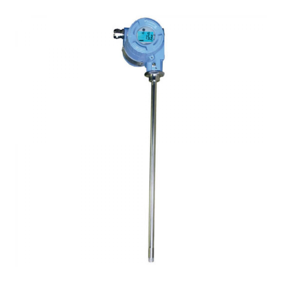
Page 9: Instrument Components
16” (406 mm) long 9” (229 mm) long Special Version MMR101R (example of order code) Instrument Components The DewPro MMR101 consists of the following components: • electronics module in industrial IP 67, type 4X enclosure • 1/2" stainless steel sensor tube •... -
Page 10: Mode Of Operation
Chapter 1. General Information Mode of Operation The DewPro MMR101 measures the relative humidity and the temperature of the process. The sensor tube is designed for direct measurement in the process (in-line measurement). The relative humidity is measured using the capacitive measuring principle. -
Page 11: Chapter 2. Installing The Dewpro Mmr101
Chapter 2. Installing the DewPro MMR101 Introduction Installing the DewPro MMR101 consists of finding a suitable installation location, mounting the unit and then making the necessary wiring connections. However, if your unit does not have a display, you should make sure the moisture units have been configured. - Page 12 Chapter 2. Installing the DewPro MMR101 Locate the four DIP switches on the printed circuit board. DIP Switches (enlarged) Use a pointed object (e.g. a screwdriver) and set switches 1-3 according to the desired output unit (see table below). Switch No. 4 has no effect.
-
Page 13: Choosing A Mounting Location
Chapter 2. Installing the DewPro MMR101 Choosing a Mounting Location Choose a mounting location that allows enough clearance for installation and convenient access during normal operation. Refer to Figure 2, below. M20 or 1/2“ NPT cable connections for DC power supply... -
Page 14: Mounting The Unit
Chapter 2. Installing the DewPro MMR101 2.3.1 Mounting the Unit CAUTION! Only trained personnel should install and operate this unit. Be sure to follow all applicable national electrical codes and safety codes when installing this unit, especially for units installed in hazardous... -
Page 15: Using A Bracket
2.3.4 Making Electrical Connections The DewPro MMR101 is a loop-powered moisture and temperature transmitter for two- or four-wire connection being supplied via the signal line (moisture signal). The first circuit transmits the moisture unit selected, the second the process temperature. The DewPro can be optionally supplied from a common or two separate power sources (1 2 ... -
Page 16: Preparation
Chapter 2. Installing the DewPro MMR101 2.3.5 Preparation Use the steps below to make electrical connections to the instrument. CAUTION! Make sure that the voltage between the + and - terminals lies between 12 and 28 V DC. Unscrew the lateral connection cover and remove from the housing. -
Page 17: System Configuration With One Or Two 24 Vdc Power Supplies
Chapter 2. Installing the DewPro MMR101 Figure 4: Terminal Block Connections The DewPro provides various options for making electrical connections. Use the appropriate section that follows to make electrical connections. 2.3.6 System Configuration with One or Two 24 VDC Power Supplies Use the figure below to make moisture and temperature connections using one or two 24 VDC power supplies. -
Page 18: System Configuration With One 24 Vdc Power Supply And Loop Powered Display
Chapter 2. Installing the DewPro MMR101 2.3.7 System Configuration with One 24 VDC Power Supply and Loop Powered Display When making electrical connection for power and the display you should adhere to the following guidelines: • The voltage between the + and - terminals must not drop below 12 V DC. -
Page 19: System Configuration With External Power Supply And Display
Chapter 2. Installing the DewPro MMR101 2.3.8 System Configuration with External Power Supply and Display Use Figure 7, below to make electrical connections for the external power supply and display. 115/230 VAC 115/230 VAC Figure 7: Connection with External Power Supply and Display... - Page 20 Chapter 2. Installing the DewPro MMR101 [no content intended for this page] DewPro MMR101 User’s Manual...
-
Page 21: Chapter 3. Operating The Mmr101
C for 4 mA (V1 H3 on matrix): Press the V key until the display shows V1. Press the H key until the display shows H3. Use the + or - key to change the numeric value to 5. DewPro MMR101 User’s Manual... - Page 22 50 = unlock Display Software System present Version Reset Error 50 = Code Reset Matrix Moisture Units: 0=% Relative Humidity3=g/m C wet bulb temp. 1=Dew Point C4=g/kg7= F wet bulb temp. 2=Dew Point F5=% by vol. DewPro MMR101 User’s Manual...
-
Page 23: Description Of Matrix Options
Location of Matrix Description of Function Measured Values Display V0 H0 Displays the measured process humidity value. The bar graph shows the output value for the programmed output range as a percentage. Selection of the Unit DewPro MMR101 User’s Manual... - Page 24 F dew point = 20 mA, default 212 V1 H6 V1 H7 = 4 mA, default 0 V1 H8 = 20 mA, default 1000 V1 H9 g/kg dry air = 4 mA, default 0 g/kg dry air = 20 mA, default 1000 DewPro MMR101 User’s Manual...
- Page 25 V3 H9 is automatically switched to the 20 mA setting. The + and - keys can be used for fine adjustment. Move on to any other matrix field to return the current value measured. DewPro MMR101 User’s Manual...
-
Page 26: Temperature Measurement Options
20 mA setting. The + and - keys can be used for fine adjustment. Move on to any other matrix field to return the output signal to reflect current measured values. Default: On instruments not equipped with display: based on order code DewPro MMR101 User’s Manual... -
Page 27: Error Codes And Messages
Below table shows the influence of temperature fluctuations of C on relative humidity. Table 8: Temperature 0,7% 0,6% 0,5% 0,5% 0,5% 3,5% 3,2% 3,0% 2,6% 2,3% 6,3% 5,7% 5,4% 4,6% 4,1% Note: The temperature loop is 0 to 150 C (32 to 300 DewPro MMR101 User’s Manual... - Page 28 Chapter 3. Operating the MMR101 [no content intended for this page] DewPro MMR101 User’s Manual...
-
Page 29: Chapter 4. Troubleshooting
The computed quantity, e.g. for the dew point, may be outside the operating range for several combinations of temperature and relative humidity Operation outside these ranges does not damage the instrument. DewPro MMR101 User’s Manual... - Page 30 If possible, blow clean air (oil- and dust-free) through the filter to loosen dirt. Note: The instrument settings and calibration data are retained in the event of a power failure thanks to storage in non-volatile memory. DewPro MMR101 User’s Manual...
-
Page 31: Chapter 5. Maintenance
This check should be performed using an GE Sensing test unit with saturated salt solutions of 11.3 and 75.4% relative humidity that can be ordered from the factory. Repairs Repairs must be carried out directly by the manufacturer or by the GE Sensing Service Engineer. DewPro MMR101 User’s Manual... - Page 32 Chapter 5. Maintenance [no content intended for this page] DewPro MMR101 User’s Manual...
-
Page 33: Chapter 6. Specifications
9-in. (228 mm) Probe: 3 in. (76 mm) to 7.25 in. (184 mm). Typical Mounting Adapter 1/2 in. tube 1/2 in. NPT-M or G1/2 compression fitting; flanges and other sizes available upon request. Sensor Guard 40 micron sintered filter, 316 stainless steel cap Weight 4.4 lbs (2 kg) DewPro MMR101 User’s Manual... - Page 34 & D, Type 4X, T4A Ta = 60°C; Dust-ignitionproof, Class II and III, Division 1,Groups E, F and G, Type 4X, T5 Ta = 60°C (FM Approvals) • MMR101-Fxxxx: Non-Sparking apparatus for ATEX Zone 2, II 3 G Ex nA IIC T4 (ATEX declaration by the manufacturer Panametrics) DewPro MMR101 User’s Manual...
- Page 35 Liability under this warranty is limited to restoring the instrument to normal operation or replacing the instrument, at the sole discretion of Panametrics. Fuses and batteries are specifically excluded from any liability. This warranty is effective from the date of delivery to the original purchaser. If Panametrics determines that the equipment was defective, the warranty period is: •...
- Page 36 • If Panametrics determines that the damage is not covered under the terms of the warranty, or if the warranty has expired, an estimate for the cost of the repairs at standard rates will be provided. Upon receipt of the owner’s approval to proceed, the instrument will be repaired and returned.
- Page 37 Contact Us! • Break/fix technical support issues for a prod- Global Technical Support Team uct you currently have Email: mstechsupport@bakerhughes.com Phone: 8000-833-9438, option 3. • RMA Repair Requests, Calibration Requests, International - Baker Hughes Customer care Document and Certificate requests for a Email: gesensingorders@bakerhughes.com product you currently have Phone: +36 27 565 314...
Need help?
Do you have a question about the DewPro MMR101 and is the answer not in the manual?
Questions and answers