
Subscribe to Our Youtube Channel
Related Manuals for Panametrics DigitalFlow XGF868i


Summary of Contents for Panametrics DigitalFlow XGF868i
- Page 1 Flow DigitalFlow™ XGF868i Flare Gas Mass Flow Ultrasonic Transmitter Startup Guide 910-198U panametrics.com August 2021...
- Page 3 Startup Guide 910-198U August 2021 panametrics.com Copyright 2021 Baker Hughes company. This material contains one or more registered trademarks of Baker Hughes Company and its subsidiaries in one or more countries. All third-party product and company names are trademarks of their respective...
- Page 4 [no content intended for this page]...
- Page 5 Preface Information Paragraphs Note: These paragraphs provide information that provides a deeper understanding of the situation, but is not essential to the proper completion of the instructions. IMPORTANT: These paragraphs provide information emphasizing instructions which are essential to proper setup of the equipment.
- Page 6 Preface WARNING! Make sure that power to the auxiliary equipment is turned OFF and locked out before you perform maintenance procedures on the equipment. Qualification of Personnel Make sure that all personnel have manufacturer-approved training applicable to the auxiliary equipment. Personal Safety Equipment Make sure that operators and maintenance personnel have all safety equipment applicable to the auxiliary equipment.
- Page 7 Preface DigitalFlow™ XGF868i Startup Guide...
- Page 8 Preface [no content intended for this page] DigitalFlow™ XGF868i Startup Guide...
-
Page 9: Table Of Contents
Contents Chapter 1. Installation Introduction ..................... .1 Unpacking . - Page 10 Contents Electronics ..................... .52 5.2.1 Flow Measurement .
-
Page 11: Chapter 1. Installation
To ensure safe and reliable operation of the XGF868i Ultrasonic Flow Transmitter, the system must be installed in accordance with the guidelines established by Panametrics engineers. Those guidelines, which are explained in detail in this chapter, include the following specific topics: •... -
Page 12: Site Considerations
Because the relative location of the flowcell and the electronics enclosure is important, use the guidelines in this section to plan the XGF868i installation. WARNING! Before beginning installation, please refer to “Installing Panametrics Measurement & Control Ultrasonic Flow Transmitters in a Potentially Hazardous Area” near the back of this manual. -
Page 13: Cable Lengths
Locate the electronics enclosure as close as possible to the flowcell and transducers, preferably directly on the flowcell. However, Panametrics can supply transducer cables up to 1000 ft (300 m) in length for remote location of the electronics enclosure. If longer cables are required, contact Panametrics for assistance. -
Page 14: Installing Temperature And Pressure Transmitters
Chapter 1. Installation Installing Temperature and Pressure Transmitters Optional temperature and pressure transmitters may be installed near the ultrasonic transducer ports as part of the flowcell. Be sure to observe the siting requirements given earlier in this chapter. These transmitters should send a 0/4-20 mA signal to the XGF868i. -
Page 15: Mounting The Xgf868I Electronics Enclosure
Refer to Figure 7 on page 21 for a complete wiring diagram. WARNING! Refer to “Installing Panametrics Measurement & Control Ultrasonic Flow Transmitters in a Potentially Hazardous Area” on page 1 near the rear of this manual for additional installation instructions. - Page 16 Chapter 1. Installation Making the Electrical Connections (cont.) WARNING! Always disconnect the line power from the XGF868i before removing either the front cover or the rear cover. This is especially important in a hazardous environment. Refer to Figure 2 below and prepare the XGF868i for wiring by completing the following steps: Disconnect any existing power line from its source.
-
Page 17: Wiring The Line Power
Line Voltage Fuse Rating 85-250 VAC Not field-replaceable (contact Panametrics) 12-28 VDC 2.0 A, Slow-Blow IMPORTANT: For compliance with the EU Low Voltage Directive (2006/95/EC), this unit requires an external power disconnect device such as a switch or circuit breaker. The disconnect device must be marked as such, clearly visible, directly accessible, and located within 1.8 m (6 ft) of the unit. -
Page 18: Wiring The Transducers And Preamplifiers
Chapter 1. Installation 1.7.1 Wiring the Line Power (cont.) Strip 1/4 in. of insulation from the end of each of the three power line leads. Route the cable through the conduit hole and connect the line power leads to terminal block TB5, using the pin number assignments shown in Figure 7 on page 21. - Page 19 Chapter 1. Installation 1.7.2.1 Local or Remote Electronics Enclosure with Local Preamplifiers WARNING! Before connecting the transducers, take them to a safe area and discharge any static buildup by shorting the center conductor of the transducer cables to the metal shield on the cable connector. IMPORTANT: The cable lengths for a given pair of transducers, including the preamplifier-to-electronics enclosure cables, must be equal to within ±4 in.
- Page 20 Refer to Figure 9 on page 23 and use the pair of coaxial cables with BNC to BNC connectors supplied by Panametrics (or equivalent cables) to connect both CH1 transducers to the dual preamplifier, using the connections on the transformer.
-
Page 21: Wiring Std 0/4-20 Ma Analog Outputs
Chapter 1. Installation 1.7.2.2 Local or Remote Electronics Enclosure with Remote Preamplifiers (cont.) Attention European Customers! To meet CE Mark requirements, all cables must be installed as described in Appendix A, CE Mark Compliance. For a 2-Channel XGF868i, repeat steps 1-3 to connect the CH2 transducers to terminal block J4 in the electronics enclosure. -
Page 22: Wiring The Serial Port
Use the serial port to connect the XGF868i flow transmitter to a printer, an ANSI terminal or a personal computer. The RS232 interface is wired as Data Terminal Equipment (DTE). Table 2 below lists the standard cables available from the factory for this purpose. Table 2: Panametrics Serial Cables Part Number PC Connector... - Page 23 Install the required cable clamp in the chosen conduit hole on the side of the electronics enclosure. Use the information in Table 3 below to construct a suitable cable for connecting the XGF868i to the external device. If desired, an appropriate cable may be purchased from Panametrics. Table 3: RS232 Connection to DCE or DTE Device...
-
Page 24: Wiring The Option Cards
Chapter 1. Installation 1.7.5 Wiring the Option Cards The XGF868i can accommodate one option card in Slot 1 and one option card in Slot 2. The following option card functions are available only in the combinations listed in Table 13: •... - Page 25 Chapter 1. Installation 1.7.5.2 Wiring a 0/4-20 mA Analog Inputs Option Card To calculate the standard flow rates, the XGF868i requires accurate temperature and pressure data from the measurement site. Transmitters installed in the flowcell can provide this information via an optional 0/4-20 mA analog inputs option card.
- Page 26 Chapter 1. Installation 1.7.5.2 Wiring a 0/4-20 mA Analog Inputs Option Card (cont.) Before making any connections, complete the steps in Preparing for Wiring on page 14. Wire the analog inputs as shown on the label in the rear cover (see Figure 8 on page 22). Note: The analog inputs option card can be calibrated with the XGF868i built-in analog outputs.
- Page 27 Chapter 1. Installation 1.7.5.4 Wiring an RTD Inputs Option Card The XGF868i RTD (Resistance Temperature Device) inputs option card provides two or four direct RTD inputs (designated as A, B, C and D). Each RTD input requires three wires, and should be connected as shown on the label in the rear cover (see Figure 2 on page 6 and Figure 8 on page 22).
- Page 28 Chapter 1. Installation 1.7.5.8 Wiring the Ethernet Interface A modified XGF868i can use the Ethernet interface to communicate to a local area network. An optional Ethernet card with a unique MAC (IP) address (installed only in slot 2) includes an RJ45 connector. To connect the Ethernet-enabled XGF868i to the network, insert the jack of an RJ45 cable into the RJ45 connector, route the cable through one of the conduit holes using an appropriate cable clamp, and wire the other end of the cable to the Ethernet network according to the manufacturer’s instructions.
- Page 29 Chapter 1: Installation Ø6.10 (155) 51° 2.06 7 PLCS (52) 3/4" NPTF 7 PLCS 3.86 (98) 3/4" NPTF 7 PLCS 8.20 (208) DETAIL A 0.52 (13) VIEW A-A 1.00 0.28 (7) (25) 0.25 (6) 1.50 (38) NOTES: 1. ALL DIMENSIONS ARE REFERENCE. 2.
- Page 30 Chapter 1: Installation .135 Ø6.10 (155) .135 R .410 2.06 (52) 51° 7 PLCS .270 .205 3.86 DETAIL C (98) 8 PLACES 3/4" NPTF 7 PLCS 8.20 (208) 1.250 5.00 1.250 DETAIL A 2.375" PIPE REF ONLY 1.250 0.52 (13) .625 SEE DETAIL C 1.00...
- Page 31 Chapter 1: Installation J2 - INPUT/OUTPUT CONNECTIONS* NOTE: For compliance with the EU Low Voltage Directive, Pin # this unit requires an external power disconnect device such as a Designation I/O1 I/O2 I/O3 I/O4 I/O5 I/O6 I/O7 I/O8 I/O9 I/O10 I/O11 I/O12 switch or circuit breaker.
- Page 32 Chapter 1: Installation ALARM A - NO OUT - A OUT - A OUT - A OUT - A OUT - A ALARM A - NO OUT - A ALARM A - COM RTN - A RTN - A RTN - A RTN - A RTN - A RTN - A...
- Page 33 Chapter 1: Installation ELECTRONICS TERMINAL BLOCK WIRING DETAIL, PRESSURE AND TEMPERATURE INPUTS CHANNEL 1 (REF ONLY) REMOTE PREAMP WITH TRANSFORMER With External Power Supply EXPLOSION-PROOF ENCLOSURE 24 VDC POWER SUPPLY – TRANSDUCERS (REF ONLY) Analog Input Transmitter Sensor + IN INPUT + –...
- Page 34 Chapter 1: Installation DigitalFlow™ XGF868i Startup Guide...
-
Page 35: Chapter 2. Initial Setup
You can program the XGF868i via either the keypad on the lower part of the glass enclosure, or PanaView™, a Panametrics PC-based, non-resident software program that communicates with the XGF868i via its RS232 serial port. PanaView supplements basic XGF868i functions with several additional capabilities. With PanaView, you can: •... -
Page 36: The Xgf868I Keypad
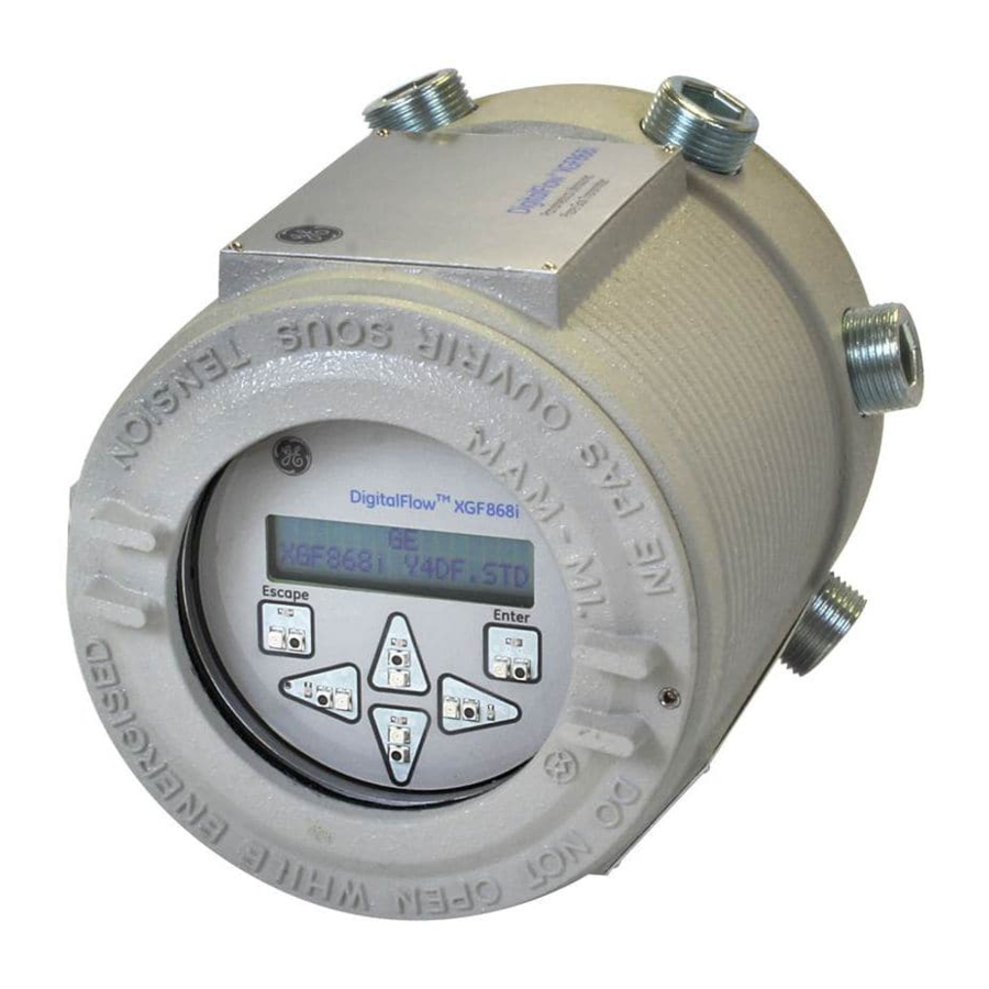
Chapter 2. Initial Setup The XGF868i Keypad Keypad Program Along with the 2-line, 16-character LCD, the XGF868i includes a 6-key magnetic keypad. The decal cutout for each key contains a hall effect sensor, pushbutton switch and visible red LED. The magnetic wand used to activate a magnetic key is found attached to the meter chassis below the front panel. - Page 37 Chapter 2. Initial Setup The XGF868i Keypad (cont.) When you power up the XGF868i, the display first shows the model and software version: Panametrics XGF868i Y4DF.STD The meter then starts to display measured parameters. 10.00 Ft/s To enter the Keypad Program, press the [Escape] key, followed by the [Enter] key, and the [Escape] key again. Each successive key must be entered within 10 seconds of the prior key.
-
Page 38: Entering Data In The Globl Menu
Chapter 2. Initial Setup Entering Data in the GLOBL Menu To begin programming your meter, you must select the system units from the GLOBL menu as discussed below. Refer to Figure 11 on page 37 and remember to record all programming data in Appendix B, Data Records. Note: Refer to the Programming Manual for information on the other submenus in the GLOBL menu. - Page 39 Chapter 2. Initial Setup 2.4.1.1 Selecting Volumetric Units Scroll to the desired Volumetric Units for the flow rate display and press [Enter]. Table 5 below lists the available volumetric units. Table 5: Available Volumetric/Totalizer Units English Metric ACF = Actual Cubic Feet ACM = Actual Cubic Meters KACF = Thousands of ACF KACM = Thousands of ACM...
- Page 40 Chapter 2. Initial Setup 2.4.1.3 Selecting Mass Flow Units Scroll to the desired Mass Flow units for the flow rate display and press [Enter]. The available units for this prompt, which are determined by the selection made at the System Units screen, are shown in Table 6 below. Table 6: Available Mass Flow Units English Metric...
-
Page 41: Activating A Channel
Chapter 2. Initial Setup Activating a Channel The Channelx-ACTIV submenu permits selection of the desired measurement method. In addition, it is used to activate/deactivate one or both of the channels in a 2-Channel XGF868i. To access the Channelx-ACTIV submenu: From the Keypad Program, scroll to CH1 or CH2 and press [Enter]. In the Channel PROGRAM menu, scroll to ACTIV and press [Enter]. -
Page 42: Entering System Data For The Channel
Chapter 2. Initial Setup Entering System Data for the Channel The Channelx-System submenu is used to enter system parameters for the channel. 2.6.1 Accessing the Channelx-System Submenu From the Channel PROGRAM menu, scroll to SYSTM and press [Enter]. The first prompt asks for the Channel Label.Use the four scrolling keys to enter the desired label (in any numeric or text combination up to five characters), and press [Enter]. -
Page 43: Selecting Mass Flow Units
Chapter 2. Initial Setup 2.6.4 Selecting Mass Flow Units Scroll to the desired Mass Flow units for the flow rate display and press [Enter]. The available units for this prompt are determined by the selection made at the System Units prompt. See Table 8 below. Table 8: Available Mass Flow Units English Metric... -
Page 44: Special Transducers
Chapter 2. Initial Setup 2.7.1 Special Transducers Scroll to the transducer Frequency (supplied by the factory) and press [Enter]. Note: The frequency is required to transmit an excitation voltage at the transducer’s natural frequency. Enter the special transducer Tw (time delay) value (supplied by the factory) and press [Enter]. Tw is the time required for the transducer signal to travel through the transducer and its cable. -
Page 45: Path And Axial Lengths
Chapter 2. Initial Setup 2.7.3 Path and Axial Lengths To enter the Path Length: Use the [] arrow key to highlight the path length unit type at the right of the screen.Then use the [] and [] arrow keys to scroll to the desired unit type. Use the [] arrow key to return to the numeric entry on the left, and enter the path length of the ultrasonic signal. - Page 46 Chapter 2. Initial Setup DigitalFlow™ XGF868i Startup Guide...
- Page 47 Chapter 2: Initial Setup [Esc] [Enter] [Esc] PROG RESET CALIB CNTRS Reset Totals (* for 2-Channel meter only) See Service Manual CH2* GLOBL DARKN LITEN STORE ABORT SYSTM COMM Meter Message System Units ACTIV SYSTM PIPE SETUP Channel Label Transducer Number English Metric Site/Channel Message...
- Page 48 Chapter 2: Initial Setup DigitalFlow™ XGF868i Startup Guide...
-
Page 49: Chapter 4. Operation
Chapter 4. Operation Chapter 4. Operation Introduction See Chapter 1, Installation, and Chapter 2, Initial Setup, to prepare the XGF868i system for operation. When the meter is ready to take measurements, proceed with this chapter. The following specific topics are discussed: •... -
Page 50: Powering Up
If the XGF868i fails any of the internal checks (see Chapter 2, Error Codes, in the Service Manual), try disconnecting the power and then repowering the unit. If the meter continues to fail any of the internal checks, contact Panametrics for assistance. After successfully performing the internal checks, the XGF868i begins taking measurements and the software version display is replaced by a measurement mode display. -
Page 51: The Lcd Display
Chapter 4. Operation The LCD Display The components of the LCD display are shown in Figure 12 below, along with a typical mass flow rate readout. Channel # Parameter CH1 MASS 4500 LB/HR XGF868i Flow Rate Units Figure 12: A Typical LCD Flow Rate Display As shown in Figure 12 above, the display screen includes the following information: •... -
Page 52: The Optional Panaview Display
Chapter 4. Operation The Optional PanaView Display The components of the PanaView text display appear in Figure 13 below, along with a typical flow rate readout. Figure 13: A Typical PanaView Text Display Pane As shown in Figure 13 above, the text pane includes the following information: •... -
Page 53: Taking Measurements
Chapter 4. Operation Taking Measurements The XGF868i is capable of displaying several different variables in a variety of formats. However, this manual discusses only the basic measurement displays using the LCD display or the PanaView display. Refer to Chapter 2, Displaying Data, in the Programming Manual for instructions on setting up alternate choices. - Page 54 Chapter 4. Operation 4.5.1 Programming the LCD (cont.) Scroll to the desired Channel option, as listed in Table 10 below. Table 10: Channel Options Option Description Channel 1 Channel 2 CH1+CH2 CH1-CH2 (CH1+CH2)/2 For each channel, select the desired Measurement Parameter, as shown in Table 11 below. Table 11: Available Measurement Parameters Option Bar Description...
- Page 55 Chapter 4. Operation Table 11: Available Measurement Parameters Option Bar Description Good Displays the compressibility. N.A. N.A. AcVOL Displays actual volumetric flow. N.A. N.A. StVOL Displays standard volumetric flow. N.A. N.A. Displays Skan transit time upstream. N.A. N.A. Tu S Displays Skan transit time downstream.
-
Page 56: Using The Lcd Display
Chapter 4. Operation 4.5.1 Programming the LCD (cont.) Note: The measurement units that appear in these prompts are those selected in the GLOBL-SYSTM menu earlier in this section. Also, when differences in one channel's programming invalidate an output previously chosen for the other, the measurement defaults to the nearest selectable item in the parameter list. -
Page 57: Panaview Display
Chapter 4. Operation 4.5.3 PanaView Display Power up PanaView, establish communications with the XGF868i and enter the required startup parameters, as described in Chapter 2, Initial Setup. Then, proceed as follows: Note: See Chapter 2, Initial Setup, in this manual and/or Chapter 1, Programming Site Data, in the Programming Manual for complete instructions on entering startup data via PanaView. - Page 58 Chapter 4. Operation 4.5.3 PanaView Display (cont.) From the expanded tree, double-click on the desired flow parameter to display it in the right pane of the window. Before actual data values can be displayed in the text pane, activate one of the following data collection modes (see Figure 15 on page 47): •...
- Page 59 Chapter 4. Operation 4.5.3.1 Displaying Multiple Process Parameters The procedure for displaying a single process parameter in a text screen may be repeated to simultaneously display multiple process parameters. To do so, proceed as follows: Display the first process parameter in a text screen, as described in the previous section. Repeat Step 1 for any desired additional process parameters, by double clicking on them in the PanaView network tree.
-
Page 60: Pausing Measurements
Chapter 4. Operation 4.5.4 Pausing Measurements On occasion, it might become necessary for the XGF868i to stop taking measurements. Through PanaView, you can direct the XGF868i to pause measurements without cutting off the power from the meter. From the meter tree in the New Meter Browser, click on the XGF868i entry. Expand the Edit Functions option, and double-click on the Pause Measurement entry. -
Page 61: Chapter 5. Specifications
High Flow Range: ±1.0 ft/s to ±394 ft/s (±0.3 to ±120 m/s) One-Path: ±2.0% Two-Path: ±1.5% Note: For 4 to 12 in. NB pipe sizes, accuracy ranges from 1.5 to 4% (consult Panametrics for details). Accuracy to ±0.5% may be achieved with calibration. 5.1.4.2 Low Flow Range: ±0.1 ft/s to ±1.0 ft/s (±0.03 to ±0.3 m/s) -
Page 62: Repeatability
Chapter 5. Specifications 5.1.7 Repeatability 5.1.7.1 High Flow Range: ±1.0 ft/s to ±394 ft/s (±0.3 to ±120 m/s) One-Path: ±0.5 to 1.0% Two-Path: ±0.35 to 0.75% 5.1.7.2 Low Flow Range: ±0.1 ft/s to ±1.0 ft/s (±0.03 to ±0.3 m/s) One-Path: ±5 to 6% Two-Path: ±3.5 to 4.0 5.1.8 Rangeability (Overall) -
Page 63: Channels
Chapter 5. Specifications 5.2.5 Channels Standard: Two channels (for two-path averaging) 5.2.6 Display 2 line x 12 character backlit LCD display, configurable to display up to four measurement parameters in sequence 5.2.7 Keypad Built-in magnetic six-button keypad for full functionality operation 5.2.8 Power Supplies Standard: 100 to 240 VAC, 50/60 Hz, ... -
Page 64: 5.2.14 Digital Interfaces
Chapter 5. Specifications 5.2.14 Digital Interfaces Standard:RS232 (PanaView (PC software) ® HART protocol on 4-20 mA output ® Optional:Modbus TCP/IP Ethernet OPC Server ® Foundation Fieldbus 5.2.15 European Compliance System: Directives EMC 2004/108/EC, LVD 2006/95/EC (Installation Category II, Pollution Degree 2) Transducers: PED Directive 97/23/EC for DN<25 [See the CE Declaration of Conformity at the back of this manual.] Wetted Ultrasonic Flow Transducers... -
Page 65: Gain
Chapter 5. Specifications 5.5.2 Gain Standard: 20 Optional: 2, 10, 40 (factory selected) 5.5.3 Temperature Range –40°F to 60°F (–40°C to 140°C) 5.5.4 Enclosure Explosion-proof: Class I, Division 1, Groups C, D (Optional: Group B upon request) ATEX Flameproof: II 2 G Ex d IIC T4, T3 or T2 Gb IECEx Flameproof: Ex d IIC T4, T3 or T2 Gb DigitalFlow™... -
Page 66: Transducer Cables
Features include site files, logs and other operations. 5.7.2 Installation Flowcells Flanged or plain-end spoolpiece, with hot tap or cold tap transducer connections Note: Consult with Panametrics for the availability of transducers and flowcells for specific applications. 5.7.3 Pressure and Temperature Transducers Available upon request. -
Page 67: Appendix A. Ce Mark Compliance
Appendix A. CE Mark Compliance Appendix A. CE Mark Compliance Introduction For CE Mark compliance, the XGF868i flow transmitter must be wired in accordance with the instructions in this appendix. IMPORTANT: CE Mark compliance is required for all units intended for use in EU countries. Wiring The XGF868i must be wired with the recommended cable, and all connections must be properly shielded and grounded. - Page 68 Appendix A. CE Mark Compliance DigitalFlow™ XGF868i Startup Guide...
-
Page 69: Appendix B. Data Records
Appendix B. Data Records Appendix B. Data Records Available Option Cards The XGF868i can hold one option card in Slot 1 and one in Slot 2. The available configurations are listed in Table 13 below. Table 13: Option Card Configurations Card # Slot # Configuration... -
Page 70: Option Cards Installed
Appendix B. Data Records Option Cards Installed Whenever an option card is installed or changed in the XGF868i flow transmitter, record the type of card and any additional setup information in the appropriate row of Table 14 below. Table 14: Option Cards Installed Slot # Type of Option Card Additional Setup Information... -
Page 71: Setup Data
Appendix B. Data Records Setup Data After the XGF868i flow transmitter has been installed, setup data must be entered via the User Program prior to operation. Record that information in Table 15 below. Table 15: Setup Data General Information Model # Serial # Software Version Setup Date... - Page 72 Appendix B. Data Records Table 15: Setup Data Channel - Pipe Parameters Channel 1 Channel 2 Trans. Type SPEC Trans. Type SPEC Transducer # Transducer # Spec. Trans. Freq. Spec. Trans. Hz Spec. Trans. Tw Spec. Trans. Tw Pipe O.D. Pipe O.D.
- Page 73 Appendix B. Data Records Table 15: Setup Data Channel - SETUP - Advanced Features - Multi K Factors (cont.) K-Factor # Velocity K-Factor K Factor # Velocity K-Factor Channel - SETUP - Advanced Features - Mass Flow Calculation Mass Flow Mass Flow Density Type Fluid Dens.
- Page 74 Appendix B. Data Records DigitalFlow™ XGF868i Startup Guide...
-
Page 75: Appendix C. Measuring P And L Dimensions
Appendix C. Measuring P and L Dimensions Appendix C. Measuring P and L Dimensions Introduction When programming the PIPE menu in the XGF868i User Program, the path length (P) and the axial dimension (L) must be entered. These parameters are determined by measurements on the actual transducer installation, with P equal to the face-to-face distance between the transducers and L equal to the axial distance between the centers of the transducer faces. - Page 76 Appendix C. Measuring P and L Dimensions Measuring P and L (cont.) 180° Installation Pipe Thickness θ Pipe O.D. θ Bias 90° Installation Figure 18: Top View of Typical Transducer Installations DigitalFlow™ XGF868i Startup Guide...
- Page 77 Index Symbols Fluid +MASS ........... . 44 Soundspeed, Entering .
- Page 78 Index Special Transducers, Entering Number ....34 Option Cards Specifications Analog Inputs ......... . 15 Electronics .
- Page 79 Index Tup ............44 Unpacking .
- Page 80 Index DigitalFlow™ XGF868i Startup Guide...
- Page 81 RETURN AUTHORIZATION NUMBER (RAN), and shipping instructions for the return of the instrument to a service center will be provided. If Panametrics Sensing instructs you to send your instrument to a service center, it must be shipped prepaid to the authorized repair station indicated in the shipping instructions.
- Page 82 Warranty DigitalFlow™ XGF868i Startup Guide...
- Page 83 Complies with IEC 60079-0: 2011 and IEC 60079-1: 2007 Manufacturer: Panametrics Sensing, Billerica, MA. • The certification covers the following Panametrics product types — XMT868, XMT868i, XGF868, XGF868i, XGN868, XGN868i, XGS868, XGS868i, XGM868, XGM868i, IGM878 &: IGM878i. • This apparatus is equipment category 2 and may be employed in Zones 1 and 2. It may not be employed in a Zone 0 area.
- Page 85 • Cable glands of an approved flameproof design are required. These must be installed according to the manufacturer’s instructions. Where the cable glands are provided by Panametrics, the manufacturer’s instructions, as supplied, to Panametrics, will be included in the documentation.
- Page 87 Panametrics Sensing 1100 Technology Park Drive Billerica, MA 01821 declare under our sole responsibility that the DigitalFlow™ XGF868i Ultrasonic Flare Gas Flow Transmitter DigitalFlow™ XGM868i Ultrasonic Gas Flow Transmitter DigitalFlow™ XGN868i Ultrasonic Natural Gas Flow Transmitter DigitalFlow™ XGS868i Ultrasonic Steam Flow Transmitter DigitalFlow™...
- Page 90 Customer Support Centers U.S.A. The Boston Center 1100 Technology Park Drive Billerica, MA 01821 U.S.A. Tel: 800 833 9438 (toll-free) 978 437 1000 E-mail: mstechsupport@bakerhughes.com Ireland Sensing House Shannon Free Zone East Shannon, County Clare Ireland Tel: +353 (0)61 470200 E-mail: mstechsupport@bakerhughes.com Copyright 2016 Baker Hughes company.
Need help?
Do you have a question about the DigitalFlow XGF868i and is the answer not in the manual?
Questions and answers
about installation for XGF868I
To install the Panametrics DigitalFlow XGF868i, follow these steps:
1. Unpack the System – Carefully remove the XGF868i components from the packaging.
2. Select Suitable Installation Sites – Choose appropriate locations for the electronics enclosure, flowcell, and transducers.
3. Install the Flowcell and Transducers – Follow the Transducer Installation Guide for precise instructions on transducer placement.
4. Install Optional Sensors – If required, install optional temperature and pressure transmitters.
5. Install the Electronics Enclosure – Secure the enclosure in a suitable location.
6. Wire the Electronics Enclosure – Connect the necessary wiring according to the system requirements.
Ensure compliance with the guidelines provided by Panametrics engineers for safe and reliable operation.
This answer is automatically generated