Table of Contents
Advertisement
Quick Links
Please follow the instructions in this manual to obtain the optimum results from this unit.
We also recommend that you keep this manual handy for future reference.
PUBLIC ADDRESS SYSTEM
T-4S60
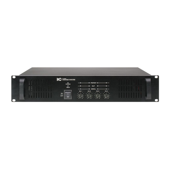
4-CHANNEL AMPLIFIER
PROTECT
POWER
CLIP
TEMP
SIGNAL
CH 1
CH 2
CH 3
CH 4
5
5
5
5
4
6
4
6
4
6
4
6
ON
3
7
3
7
3
7
3
OFF
2
8
2
8
2
8
2
1
9
1
9
1
9
1
0
10
0
10
0
10
0
10
T-4S120
4-CHANNEL AMPLIFIER
PROTECT
POWER
CLIP
TEMP
SIGNAL
CH 1
CH 2
CH 3
CH 4
5
5
5
5
4
6
4
6
4
6
4
6
ON
3
7
3
7
3
7
3
2
8
2
8
2
8
2
OFF
1
9
1
9
1
9
1
0
10
0
10
0
10
0
10
T-4S240
4-CHANNEL AMPLIFIER
PROTECT
POWER
CLIP
TEMP
SIGNAL
CH 1
CH 2
CH 3
CH 4
5
5
5
5
4
6
4
6
4
6
4
6
3
7
3
7
3
7
3
2
8
2
8
2
8
2
ON
1
9
1
9
1
9
1
0
10
0
10
0
10
0
10
OFF
T-4S120
T-4S240
4-CHANNEL AMPLIFIER
7
8
9
7
8
9
7
8
9
T-4S60
Advertisement
Table of Contents

Related Manuals for ITC T-4S60


Summary of Contents for ITC T-4S60
- Page 1 PUBLIC ADDRESS SYSTEM T-4S60 T-4S120 T-4S240 4-CHANNEL AMPLIFIER T-4S60 4-CHANNEL AMPLIFIER PROTECT POWER CLIP TEMP SIGNAL CH 1 CH 2 CH 3 CH 4 T-4S120 4-CHANNEL AMPLIFIER PROTECT POWER CLIP TEMP SIGNAL CH 1 CH 2 CH 3 CH 4...
-
Page 2: Table Of Contents
..................3 2. GENERAL DESCRIPTION ...................5 3. FEATURES ......................5 4. NOMENCLATURE AND FUNCTIONS 4.1 T-4S60-4S120Front Panel ..................6 4.2 T-4S60-4S120Rear Panel ................... 7 4.3 T-4S240 Front Panel ....................8 4.4 T-4S240 Rear Panel ....................9 5. CONNECTIONS 5.1 Speaker Connections ....................10 5.2 Input Connections .....................10 6. -
Page 3: Safety Precautions
1. SAFETY PRECAUTIONS Be sure to read the instructions in this section carefully before use. Make sure to observe the instructions in this manual as the conventions of safety symbols and messages regarded as very important precautions are included. We also recommend you keep this instruction manual handy for future reference. Safety Symbol and Message Conventions Safety symbols and messages described below are used in this manual to prevent bodily injury and property damage which could result from mishandling. - Page 4 When removing the power cord, be sure to hold its plug to pull. Contact your ITC dealer as to the cleaning. If dust is allowed to accumulate in the unit over a long Do not block the ventilation slots in the unit's cover.
-
Page 5: General Description
2. GENERAL DESCRIPTION With four separate power amplififers in a single chassis and power ratings from 60 to 240 watts RMS, these sleek, attractive units provide a compact solution for PA system amplification and distribution. Each channel has its own input and 4ohm,70V and 100V speaker outputs,so a wide variety of audio sources and speaker zones can be easily configured. -
Page 6: Nomenclature And Functions
4. NOMENCLATURE AND FUNCTIONS 4.1 T-4S60-4S120 FRONT PANEL PROTECT POWER CLIP TEMP SIGNAL CH 1 CH 2 CH 3 CH 4 1. POWER SWITCH On top of the opening Power Press the end, power shut down 2. CH1\CH2\CH3\CH4 VOLUME Channel volume control SIGNAL Signal indicator LED When lit input signal is detected. -
Page 7: T-4S60-4S120Rear Panel
NOMENCLATURE AND FUNCTIONS T-4S60-4S120 REAR PANEL CH 1 OUT CH 2 OUT CH 1 IN CH 2 IN 2-HOT+ 3-COLD- ¦¸ ¦¸ ¦¸ ¦¸ 1-GND CH 3 OUT CH 4 OUT CH 3 IN CH 4 IN ¦¸ ¦¸ ¦¸... -
Page 8: T-4S240 Front Panel
NOMENCLATURE AND FUNCTIONS 4.3 T-4S240 FRONT PANEL PROTECT POWER CLIP TEMP SIGNAL CH 1 CH 2 CH 3 CH 4 1. POWER SWITCH On top of the opening Power Press the end, power shut down 2. CH1\CH2\CH3\CH4 VOLUME Channel volume control SIGNAL Signal indicator LED When lit input signal is detected. -
Page 9: T-4S240 Rear Panel
NOMENCLATURE AND FUNCTIONS T-4S240 REAR PANEL 2-HOT+ 3-COLD- 1-GND CH 1 OUT CH 2 OUT CH 1 IN CH 2 IN T12AL 250V ¦¸ ¦¸ CH 3 OUT CH 4 OUT CH 3 IN CH 4 IN ¦¸ ¦¸ 8. ~220-240V 50/60Hz POWER INPUT 9. -
Page 10: Connections
5. CONNECTIONS 5.1 SPEAKER CONNECTIONS 70V 100V 70V 100V 70V 100V (T-4S60) (T-4S60) (T-4S120) (T-4S120) (T-4S240) (T-4S240) 100V LINE 70V LINE 70V/ 5.2 XLR CONNECTIONS... -
Page 11: Applications
6. APPLICATIONS REAR PANEL CONNECTIONS... - Page 12 APPLICATIONS REAR PANEL CONNECTIONS...
-
Page 13: Block Diagram
7. BLOCK DIAGRAM... -
Page 14: Specifications
8. SPECIFICATIONS MODEL T-4S60 T-4S120 T-4S240 RATED POWER OUTPUT 4X60W 4X120W 4X240W SPEAKER OUTPUTS 4~16 ,70V/100V OUTPUTS NOISE <3mV IMPEDANCE 200:1 INPUT SENSITIVITY 775mV/0dB 50Hz~16KHz d istortion<1.5Db FREQUENCY RESPONSE S/N RATIO >15V/microsecond T.H.D <1% Copulsive wind cool form COOL METHOD... -
Page 15: Dimensional Diagram
9. DIMENSIONAL DIAGRAM UNIT :mm PROTECT POWER CLIP TEMP SIGNAL CH 1 CH 2 CH 3 CH 4 CH 1 OUT CH 2 OUT CH 1 IN CH 2 IN 2-HOT+ 3-COLD- ¦¸ ¦¸ ¦¸ ¦¸ 1-GND CH 3 OUT CH 4 OUT CH 3 IN CH 4 IN... - Page 16 DIMENSIONAL DIAGRAM UNIT :mm PROTECT POWER CLIP TEMP SIGNAL CH 1 CH 2 CH 3 CH 4 2-HOT+ 3-COLD- 1-GND CH 1 OUT CH 2 OUT CH 1 IN CH 2 IN T12AL 250V ¦¸ ¦¸ CH 3 OUT CH 4 OUT CH 3 IN CH 4 IN ¦¸...
- Page 17 PUBLIC ADDRESS SYSTEM PUBLIC ADDRESS SYSTEM VersionV0.2...
Need help?
Do you have a question about the T-4S60 and is the answer not in the manual?
Questions and answers