Table of Contents
Advertisement
Quick Links
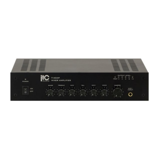
PUBLIC ADDRESS SYSTEM
T-40AP
MIXER AMPLIFIER
POWER
BASS
TREBLE
0
-1
+1
-1
ON
-2
+2
-2
OFF
-3
+3
-3
-4
+4
-4
-5
+5
-5
Please follow the instructions in this manual to obtain the optimum results from this unit.
We also recommend that you keep this manual handy for future reference.
AUX
TEL
MIC1
0
5
5
5
+1
4
6
4
6
4
6
+2
3
7
3
7
3
7
3
+3
2
8
2
8
2
8
2
+4
1
9
1
9
1
9
1
+5
0
10
0
10
0
10
T-40AP
MIXER AMPLIFIER
OUTPUT LEVEL
PROT
2
4
6
8
10
MASTER
MIC2
5
4
6
5
MIC1
4
6
3
7
INPUT
7
2
8
8
9
1
9
0
10
0
10
Advertisement
Table of Contents

Related Manuals for ITC T-40AP


Summary of Contents for ITC T-40AP
- Page 1 PUBLIC ADDRESS SYSTEM T-40AP MIXER AMPLIFIER OUTPUT LEVEL T-40AP MIXER AMPLIFIER PROT POWER MASTER BASS TREBLE MIC1 MIC2 MIC1 INPUT Please follow the instructions in this manual to obtain the optimum results from this unit. We also recommend that you keep this manual handy for future reference.
-
Page 2: Table Of Contents
TABLE OF CONTENTS 1. SAFETY PRECAUTIONS ..................3 2. FEATURES .......................5 3. NOMENCLATURE AND FUNCTIONS Front Panel ......................6 3.2 Rear Panel......................7 4. CONNECTIONS 4.1. Speaker Connections .....................8 4.2. XLR Connections ....................8 5.MACHINE OPERATION ...................9 6.APPLICATIONS .......................10 7. BLOCK DIAGRAM .................... -
Page 3: Safety Precautions
1. SAFETY PRECAUTIONS Be sure to read the instructions in this section carefully before use. Make sure to observe the instructions in this manual as the conventions of safety symbols and messages regarded as very important precautions are included. We also recommend you keep this instruction manual handy for future reference. Safety Symbol and Message Conventions Safety symbols and messages described below are used in this manual to prevent bodily injury and property damage which could result from mishandling. - Page 4 SAFETY PRECAUTIONS When the Unit is in Use When Installing the Unit Do not place heavy objects on the unit as this may Never plug in nor remove the power supply plug cause it to fall or break which may result in with wet hands, as doing so may cause electric personal injury and/or...
-
Page 5: Features
2. FEATURES 1. Rated Power:40W. 2. 100V,70V constant voltage outputs and 4~16Ohms constant resistance output. 3. 1 channel MIC2 one-port input (5mv 1Kohms) and 1 channel (300mv 10Kohms) AUX input 4. 1 channel MIC1 balanced/unbalanced input (2.5/5mv 1/2Kohms) 5. 1 channel TEL input (sensitivity 1V 2Kohms) 6. -
Page 6: Nomenclature And Functions
3. NOMENCLATURE AND FUNCTIONS 3.1 FRONT PANEL OUTPUT LEVEL PROT POWER MASTER BASS TREBLE MIC1 MIC2 MIC1 INPUT 1. POWER SWITCH 6. TEL TEL volume control On top of the opening Power Press the end, power shut down 7. MIC1 \MIC2 2. -
Page 7: Rear Panel
NOMENCLATURE AND FUNCTIONS 3.2 REAR PANEL MIC 1 MIC 1 LINE INTERRUPT XLR/6.30 INPUT MIC 2 TIME A D J TEL INPUT OUTPUT COM 4-16Ω 70V 100V +48V BAL / UNBAL PHANTOM 14 15 16 12. MUTE ADJUSTOR 16. TEL INPUT Adjust the mute degree from 0- Line output 20dB when MIC1 input override all... -
Page 8: Connections
4. CONNECTIONS 4.1 SPEAKER CONNECTIONS COM 4-16 70V 100V COM 4-16 70V 100V COM 4-16 70V 100V T-40AP T-40AP 100V LINE 4-16Ω 70V LINE 70V/ 4.2 XLR CONNECTIONS... -
Page 9: Machine Operation
5. MACHINE OPERATION OPERATION ATTENTION MUTE FUNCTION The four output connectors only can choose two 1. Tel has priority over all inputs. connectors work together. If voltage is 70V/100V, 2. MIC 1 is second priority, adjust mute electric the speakers must be with transformer and make potential can override other input signal except sure the total power wattage of speaker is 15% tel signal. -
Page 10: Applications
6. APPLICATIONS... -
Page 11: Block Diagram
7. BLOCK DIAGRAM... -
Page 12: Specifications
8. SPECIFICATIONS MIXER AMPLIFIER WITH CD T-40AP Model Speaker Line Input 4~16Ω,70V,100V Amplifier Section(amp In @ 1khz,8ohm Load Output) Rated maximum output power (THD 1%) Input sensitivity/impedance 1V/20Kohms Frequency response(At 1KHz Half power output) 80Hz~16KHz(+1dB/-3 MIC1~2 input section( MIC in@1Khz, preamp out) -
Page 13: Dimensional Diagram
9. DIMENSIONAL DIAGRAM UNIT :mm OUTPUT LEVEL PROT POWER MASTER BASS TREBLE MIC1 MIC2 MIC1 INPUT MIC 1 MIC 1 LINE INTERRUPT XLR/6.30 INPUT MIC 2 TIME A D J TEL INPUT OUTPUT COM 4-16Ω 70V 100V +48V BAL / UNBAL PHANTOM UNIT :mm OUTPUT LEVEL... - Page 14 PUBLIC ADDRESS SYSTEM VersionV0.1...
Need help?
Do you have a question about the T-40AP and is the answer not in the manual?
Questions and answers