Table of Contents
Advertisement
Quick Links
Advertisement
Table of Contents

Subscribe to Our Youtube Channel
Related Manuals for Bolt VM-1000C


Summary of Contents for Bolt VM-1000C
- Page 1 VM-1000 TTL MACRO FLASH SET User Manual...
-
Page 2: Table Of Contents
Thank you for choosing Bolt. Table of Contents The Bolt VM-1000 is a full-featured wireless macro Precautions ............3 flash for your Nikon, Canon, or Sony camera. This Contents ...............5 advanced digital flash system puts creative control Overview ..............6 in your hands with a broad range of automatic and manual features. -
Page 3: Precautions
Precautions ⚠ ⚡ • Before using this product, please thoroughly read the • Keep this product and its batteries out of the reach of following safety notices to ensure safe use and help children. prevent damage to your flash or injury to yourself and •... - Page 4 • Do not use or store this product in flammable conditions • Should the product sustain physical damage, do not (such as environments containing flammable gases or touch any exposed interior metal parts. If touched, they liquid chemicals). This can damage the flash, start a fire, may generate an electric shock or cause a malfunction.
-
Page 5: Contents
Contents • Keep the metal contacts in the battery compartment • VM-1010 TTL Macro Flash (×2) clean and free of corrosion and dirt. Do not touch them • VM-1020 TTL Transceiver with your fingers. Corrosive elements on the contacts • Flash mounting ring can damage this product and prevent it from functioning •... -
Page 6: Overview
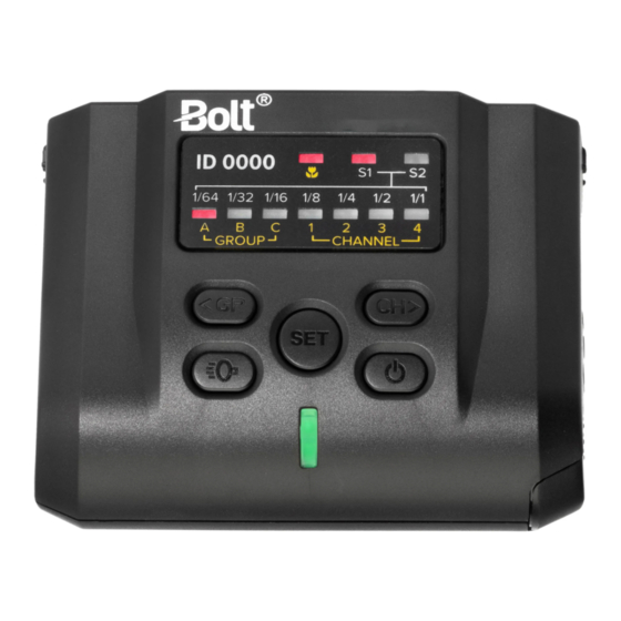
Overview Macro Flash VM-1010 Group LED indicators Mounting foot Luminance LED indicators Flash sensor Macro TTL LED indicator LED assist lamps S1/S2 LED indicators Diffuser notches Channel LED indicators USB interface Group / < button Slide release LED focus assist light / flash test button Set button Power button Channel / >... - Page 7 ID 0000 1/64 1/32 1/16 1/8 GROUP CHANNEL Overview...
- Page 8 Transceiver VM-1020 Power button Battery compartment button LED focus assist button Battery compartment door Flash test LED indicator/button LED focus assist Adjustment dial Mounting foot Info button Collar-lock release button Mode button Foot-collar lock Set button USB port Group button 2.5 mm shutter-release sync port 1/4-20 socket Hot shoe...
- Page 9 Overview...
- Page 10 Flash Mounting Ring Flash Stand Ring release button (×2) Cold shoe Flash holder ring 1/4-20 socket Foot mount Diffuser Notch windows Shoe Adapter Foot mount Locking wheel Mounting foot Overview...
- Page 11 Overview...
-
Page 12: Battery Installation
Battery Installation VM-1010 1. Push and slide out the battery compartment door in the direction of the arrow. 2. Insert the batteries with the correct polarity orientation. 3. Slide the battery door closed until it’s secure. Battery Installation... - Page 13 VM-1020 1. Press the battery compartment button to open the door. 2. Insert the batteries on top of the release pull, with the correct polarity as shown inside the compartment. 3. Close the compartment door until secure. Note: When the batteries are low on power, the battery icon will blink.
-
Page 14: Transceiver And Flash Setup
Transceiver and Flash Setup Mounting the Transceiver to a Camera 1. Press the collar-lock release button, and slide the collar to the left to unlock. 2. Insert the mounting foot into your camera’s hot shoe. 3. Slide the collar to the right until it clicks and is locked. - Page 15 Light Stand You can mount the transceiver to a light stand, using the mini-stand or transceiver’s 1/4-20 socket. 1. Screw the mini stand on to a light stand using the 1/4-20 mount. 2. Attach the transceiver to the mini-stand’s cold shoe, and slide the collar lock to the right until secure.
- Page 16 Mounting the Macro Flash Setting Up the Flash Mounting Ring 1. Choose the lens adapter (52, 55, 58, 62, 67, 72, or 77 mm) that fits your lens, and screw it onto the lens’s filter threads. 2. Squeeze the ring release buttons, seat the flash mounting ring over the lens adapter, and release.
- Page 17 3. Seat the flash’s mounting foot into the ring’s flash holder, and slide the foot lock down to secure. Use the slide release buttons to adjust the flash’s postion around the ring. Mounting the Flash to the Flash Stand 1. Hook the flash’s mounting foot into the stand, and seat the foot into the flash stand.
- Page 18 Using the Shoe Adapter 1. Hook the flash’s mounting foot into the shoe adapter’s foot mount. 2. Slide the lock down to secure. 3. Slide the shoe adapter’s foot into the cold shoe of the flash stand. 4. Rotate the locking wheel clockwise until secure. Adjusting the Flash Angle You can adjust the flash head to angles of -45°...
- Page 19 Attaching a Diffuser Diffuser Attach the diffuser over the diffuser notches. Make sure they line up with the diffuser notch windows. Soft Diffuser You can attach the soft diffuser over the diffuser or directly to the flash head. Make sure the soft diffuser is in the correct orientation. Using the Gels A collection of nine color gels are included with each flash, so you can change the flash color temperature.
-
Page 20: Vm-1010 Flash Settings And Controls
VM-1010 Flash Settings and Controls TTL/Macro Mode Press and hold the power button [ ] to turn the flash on. LED indicators will light up for TTL/Macro mode, Group A, and Channel 1. To cycle through groups A, B, and C, press Group [ ]. - Page 21 S1/S2 Slave Modes In the S1/S2 Slave modes, the VM-1010 is set to be optically triggered by an external flash source. The S1 mode fires on any flash, while the S2 mode ignores the preflash and fires on the second flash. You will set the flash power manually when using these modes.
-
Page 22: Vm-1020 Transceiver Settings And Controls
VM-1020 Transceiver Settings and Controls Press and hold the power button [ ] until the Flash Test button lights up, and the LCD displays the flash settings. Any changes to the settings will be saved after eight seconds of inactivity. Pressing the Info [ ] and Mode [ ] buttons at the same time will reset all setting and parameter changes. - Page 23 1. Press the Mode [ ] button to switch to Group mode. 2. Press the Group [ ] button to highlight and enter group selection, and use the Adjustment dial to select the groups A/B/C. Make sure the VM-1010 flashes are set to the same group. 3.
- Page 24 Global EV Setting the Wireless Channel 1. Press the Info [ ] button once, and the wireless +0.1 GROUP channel will blink. Use the adjustment dial to 1/128 Auto +0.3 Auto change the channel from 1 to 16. +0.3 Auto 2.
- Page 25 1. Press the Info [ ] button twice until the first 0 of the ID is blinking. Use the adjustment dial to change values. 2. Press the Info [ ] button again for each additional digit of the ID, and use the adjustment dial to change the value.
- Page 26 Multi Mode Multi Mode (Canon Only) Multi mode fires the flash repeatedly during a single MULTI exposure, creating a multi-exposure effect. Use this 1/32 015 180Hz 1/64 feature to capture stroboscopic photos of a dancer 1/128 leaping across a stage or a golfer swinging a driver. MASTER CH01 9999 To use Multi mode, you’ll need a second VM-1020...
- Page 27 3. Press the Set [ ] button to highlight and change the flash group’s power. Use the Adjustment dial to select the power level in six steps from 1/4 to 1/128. 4. Press the Info [ ] button until the number of shots is flashing. Use the Adjustment dial to select the number of shots from 0 to 90 (selection is based on the camera’s shutter speed).
- Page 28 TTL Mode TTL Ratio Mode This mode allows you to set power ratios between +0.1 ITTL groups A and B. Group C works independently and Auto offers TTL, manual, or off modes. For example, if you +0.3 85mm set a ratio of 1:2 between groups A and B, group B will MASTER CH01 9999 fire with two times more power than group A.
- Page 29 5. Press the Set [ ] button again to confirm the group A:B settings. You can change Group C settings according to the instructions in Group Mode above. To set the wireless channel and ID number, as well as the overall group compensation, see Setting the Wireless Channel, Setting the Wireless ID, and Global EV Compensation above.
- Page 30 1. With the unit powered on, press the power [ ] button once to enter Slave mode. 2. Press the Group [ ] button to cycle through groups A/B/C. 3. Press the Info [ ] button to change the wireless channel and ID (see Setting the Wireless Channel and Setting the Wireless ID above).
- Page 31 Flash Test Press the Flash Test [ ] button to fire off a test flash from all the flashes in your setup. This ensures everything is linked correctly. Triggering a Studio Light You can wirelessly trigger a studio light using the VM-1020’s 2.5 mm sync port and the master/slave setup between multiple transceivers.
-
Page 32: Specifications
Specifications Transceiver (VM-1020) Operating Frequency: 2.4 GHz Input Voltage: Operating Distance: 98 ft. (30 m) Operating Temperature: 5°F to 149°F (-15°C to 65°C) Groups: Storage Temperature: -22°F to 185°F (-30°C to 85°C) Channels: Dimensions (H × W × D): 2.1 × 2.5 × 3.3 in. Battery Type: (5.4 ×... - Page 33 Macro Flash (VM-1010) Guide Number: 10 (ISO 100 m) / 14 (ISO 200 m) Operating Temperature: 10°F to 122°F LED Light: 0.5 W, 5500 K ±200 K, RA 90 (-10°C to 50°C) Groups: Storage Temperature: -4°F to 158°F (-20°C to 70°C) Channels: Dimensions (H ×...
-
Page 34: Troubleshooting
Troubleshooting Problem Solution The VM-1000 does Replace the batteries. (Note: If the batteries are low, replace both batteries at the same time. Do not not turn on. use different brands or types of batteries.) Make sure that the batteries are inserted into the battery compartment with the correct polarity orientation. -
Page 35: Firmware Upgrade
Firmware Upgrade FCC Compliance Visit www.boltflashes.com for more information on This device complies with Part 15 of the FCC Rules. the latest firmware version. Operation is subject to the following two conditions: Connect the VM-1010’s and VM-1020’s USB ports to a 1. - Page 36 To obtain warranty coverage, contact the BOLT Customer Service Department to obtain a return merchandise authorization (“RMA”) number, and return the defective product to BOLT along with the RMA number and proof of purchase. Shipment of the defective product is at the purchaser’s own risk and expense.
Need help?
Do you have a question about the VM-1000C and is the answer not in the manual?
Questions and answers