
Subscribe to Our Youtube Channel
Related Manuals for Bolt VC-310


Summary of Contents for Bolt VC-310
- Page 1 Inspiration strikes Inspiration strikes VC-310 COMPACT ON-CAMERA TTL FLASH User’s Manual...
- Page 2 Copyright © 2016 Gradus Group. Bolt and other names of Bolt products are trademarks of Gradus Group. Other product and corporate names mentioned herein are trademarks of their respective holders.
- Page 3 Introduction Thank you for choosing Bolt. The VC-310 is a compact, full-featured shoe-mount flash for your Sony, Olympus/ Panasonic, or Fujifilm camera. This advanced digital flash puts creative control in your hands with a broad range of automatic and manual features. It can be used as both an on-camera flash and a wireless slave flash. Among the benefits you’ll enjoy:...
-
Page 4: Table Of Contents
Contents Overview ..............................6-7 Warnings ..............................8-9 Installing Batteries ............................10 Mounting the Flash ............................11 Turning On the Flash and Firing a Test Shot ....................12-14 Extended Interface ............................14 Automatic TTL Flash Mode ........................15-16 Using Flash Exposure Compensation ......................16 Manual Flash Mode ..........................17-18 Diffusing the Flash ............................ - Page 5 Specifications ..............................27 Troubleshooting ............................28-29 FCC Compliance ............................30 One-Year Limited Warranty ..........................31 Contents...
- Page 6 16 16 Overview...
-
Page 7: Overview
Overview 16. Optical sensor Flash head 17. Battery compartment Flash test button with cover Mode button 18. Flash stand Flash ready indicator 19. Diffuser Left arrow 20. Carrying pouch Set button Right arrow F1 function button F2 function button 10. Power button 11. -
Page 8: Warnings
Warnings Before using your VC-310, please read the following safety notices thoroughly to ensure safe use and to help prevent damage to your flash or injury to yourself or others. • Do not fire the flash at close range directly into the eyes of people or animals. - Page 9 • This product is not water resistant. Keep it away from rain, snow, humidity, and general moisture. • Should the VC-310 sustain physical damage, do not touch any exposed interior metal parts. If touched, they may generate an electric shock or cause a malfunction. Promptly remove the batteries and take the product to an authorized service center for repair.
-
Page 10: Installing Batteries
Installing Batteries The VC-310 can be powered by two AA batteries of several types: • Lithium (1.5 V) • Nickel-metal hydride (NiMH) (1.2 V) • Alkaline (1.5 V) Turn the flash upside down. Press the button on the battery compartment cover so the cover flips open. -
Page 11: Mounting The Flash
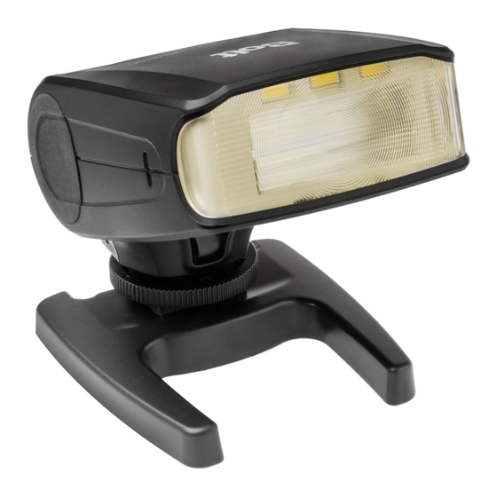
Mounting the VC-310 on the included stand adapter: You can mount the VC-310 on the included stand adapter in the same way you would mount it on your camera. This allows you to set the flash up on a flat surface or attach it to a tripod head, light stand, or clamp that has a compatible 1/4"-20 screw mount. -
Page 12: Turning On The Flash And Firing A Test Shot
Sleep mode: After approximately two minutes of inactivity, the flash will automatically enter sleep mode to conserve the battery life by turning off the LCD and flash ready light. To reactivate the VC-310, press the Set button on the flash unit or press your camera’s shutter-release button halfway. During long periods of inactivity, use the power switch to turn the flash off completely. - Page 13 Overheating protection mode: If the operating temperature of the VC-310 is too high after several full-power flashes, the flash will enter the overheating protection mode. The thermal warning indicator [TP-HI] will appear on the LCD, and you should let the flash cool down for a period of 2–5 minutes.
-
Page 14: Extended Interface
Micro-B USB: This flash supports firmware upgrades through the micro USB port on the side of the flash. In order to ensure compatibility with future cameras, the VC-310’s firmware may be updated. This can be done to ensure proper communication with new cameras or to add new features. Visit www.boltflashes.com/firmware to check if a new firmware version has been released. -
Page 15: Automatic Ttl Flash Mode
ISO value Aperture value When the VC-310 is mounted on a compatible TTL camera, it can set the appropriate flash level automatically, in conjunction with the camera’s through-the-lens (TTL) metering system. To use the automatic TTL flash mode, mount the flash on the camera and follow these steps: Turn the flash on and press the Mode button repeatedly to cycle through the flash modes until the TTL mode indicator appears on the LCD. -
Page 16: Using Flash Exposure Compensation
In automatic TTL mode, you can use flash exposure compensation to incrementally alter the VC-310’s flash output, just as you would change exposure with the exposure compensation function on your camera. -
Page 17: Manual Flash Mode
Manual flash output power You can set the VC-310’s flash output level manually, for greater creative control over your images. The 1/1 setting is the full-power flash, and each successive setting halves the light output, all the way down to 1/128. -
Page 18: Diffusing The Flash
Press the right or left arrows to increase or decrease to the desired flash output level. Press the Set button to confirm. Press your camera’s shutter release button to take the picture. Adjust your camera’s exposure settings and the flash’s light output level as needed. When adjusting exposure settings on your camera, the highest shutter speed available will be your camera’s flash sync speed. -
Page 19: Bouncing Your Flash
Bouncing Your Flash The VC-310 flash head can tilt down to -7° and up at 45°, 60°, 75°, and 90° angles to the lens. It can also swivel horizontally 90° to the right and 60° to the left. Using flash to directly illuminate a subject often creates harsh, unnatural, and unattractive shadows. The flash can be tilted or swiveled, allowing you to aim your flash at a large white or neutral-colored surface, such as a ceiling, wall, or reflector. -
Page 20: Stroboscopic Mode (Vc-310Smi And Vc-310Op Models Only)
Stroboscopic Mode (VC-310SMI and VC-310OP models only) Overview • Multi flash mode MULTI • Multi power output Stroboscopic flash indicator 1/128 5T−7Hz • Time (number of flashes) Stroboscopic output power • Flash frequency IS0100 F5 6 Time (number of flashes) TIME Flash frequency The stroboscopic mode fires the flash multiple times in quick succession during a single exposure. - Page 21 Press the Set button to highlight the flash output power level, and adjust with the right and left arrows. Press the Set button to confirm. Press the F1 function button to change the Time. This will set the number of flashes that fire per exposure.
- Page 22 This works optically—when the VC-310 “sees” another flash firing, it will instantaneously fire along with it. In order to ensure that the VC-310 fires at the correct time, there are two different slave modes available: S1 and S2.
-
Page 23: Manual Optical Slave Modes S1/S2
To set the VC-310 to manual optical slave mode S1/S2, follow these steps: Press the Mode button repeatedly until the S1 or S2 indicator appears on the LCD. VC-310F and VC-310OP: Press the Set button to highlight the output level. -
Page 24: Positioning The Slave And Remote Flash Units
Positioning the Slave and Remote Flash Units You can create various professional lighting setups by positioning slave units individually or in groups to function as main, fill, accent, and other lights. Metering your scene with a handheld light meter and setting your light ratios to achieve specific looks will give you a professional level of creative control. - Page 25 • The wireless optical TTL sensor is located on the front of the VC-310. Make sure that the sensor is facing the master flash and that there are no obstructions between the two units. • When photographing outdoors or in bright ambient light, the optical sensors may be overwhelmed by ambient light, which will lower their sensitivity.
-
Page 26: Stroboscopic Reference
Stroboscopic Reference This chart shows the maximum number of flashes possible for any given frequency/flash output combination. Flash Output/Hz 1/16 1/32 1/64 1/128 20–100 Stroboscopic Reference... -
Page 27: Specifications
Specifications Type On-camera and wireless TTL automatic and manual flash VC-310F: Fujifilm models with support for Fujifilm TTL flash systems VC-310OP: Panasonic and Olympus models with support for Panasonic and Olympus Compatible cameras TTL flash systems VC-310SMI: Sony models with support for P-TTL flash systems Guide number (at 50 mm focal length, ISO 100) GN 32 Flash recycle time... -
Page 28: Troubleshooting
Troubleshooting Problem Solution The flash is stuck in the camera Make sure that the locking wheel is released (page 11). hot shoe. The flash is turned on but • Make sure that fresh batteries are installed and in the proper won’t fire. - Page 29 Problem Solution The flash is set up as a wireless • Make sure that the master flash is within the transmission range, slave, but the light is not and that the wireless sensor on the slave is pointing toward the noticeable in the picture.
-
Page 30: Fcc Compliance
FCC Compliance This device complies with Part 15 of the FCC Rules. Operation is subject to the following two conditions: This device may not cause harmful interference. This device must accept any interference received, including interference that may cause undesired operation. FCC Compliance... -
Page 31: One-Year Limited Warranty
To obtain warranty coverage, contact the BOLT Customer Service Department to obtain a return merchandise authorization (“RMA”) number, and return the defective product to BOLT along with the RMA number and proof of purchase. Shipment of the defective product is at the purchaser’s own risk and expense. - Page 32 www.boltflashes.com...
Need help?
Do you have a question about the VC-310 and is the answer not in the manual?
Questions and answers