
Subscribe to Our Youtube Channel
Related Manuals for Pottinger CAT 230 plus


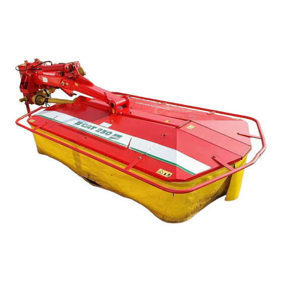
Summary of Contents for Pottinger CAT 230 plus
- Page 1 99 331.GB.809.1 CAT 230 plus (Type PTM 331 : + . . 01001) CAT 230 plus Conditioner (Type PTM 331 : + . . 01001) Drum mower Ihre / Your / Votre • Masch.Nr. • Fgst.Ident.Nr.
- Page 2 Dear Farmer You have just made an excellent choice. Naturally we are very happy and wish to congratulate you for having chosen Pöttinger. As your agricultural partner, we offer you quality and efficiency combined with reliable servicing. In order to assess the spare-parts demand for our agricultural machines and to take these demands into consideration when developing new machines, we would ask you to provide us with some details.
- Page 3 INSTRUCTIONS FOR Dokument PRODUCT DELIVERY ALOIS PÖTTINGER Maschinenfabrik GmbH GEBR. PÖTTINGER GMBH A-4710 Grieskirchen Servicezentrum Tel. (07248) 600 -0 D-86899 Landsberg/Lech, Spöttinger-Straße 24 Telefax (07248) 600-511 Telefon (0 81 91) 92 99-130 / 231 Telefax (0 81 91) 59 656 GEBR.
-
Page 4: Table Of Contents
TABLE OF CONTENTS Attention! WARNING SIGNS CE sign ................5 Meaning of warning signs ..........5 TECHNICAL DATA Technical data ............... 6 Optional extra: ............... 6 TRAKANBAU Attachement ..............7 To swing mounting frame up .......... 7 Set lower link pin on mounting frame accordingly..8 Lower link pin (990mm - 1040mm) standard .... -
Page 5: Warning Signs Attention
WARNING SIGNS CE sign The CE sign, which is affixed by the manufacturer, indicates outwardly that this machine conforms to the engineering guideline regulations and the other relevant EU guidelines. EU Declaration of Conformity (see supplement) By signing the EU Declaration of Conformity, the manufacturer declares that the machine being brought into service complies with all relevant safety and health requirements. -
Page 6: Technical Data
TECHNICAL DATA Technical data CAT 230 (Type PTM 331) Working width 2,25 m Coverage up to 2,5 ha/h nu.of drums no.of blades per drum maximum power take-up at p.t.o. 44 KW(60 HP) maximum power take-up with conditioner 59 KW(80 HP) maximum p.t.o speed 540 rpm transport width... -
Page 7: Trakanbau
TRAKANBAU Attachement Safety hints: see supplement-A1 points 8a. - h.) To swing mounting frame up - Connect the Hydraulic socket gear (60) to the swivel cylinder. - Pull out the supporting feet and secure them with the cotter pin. TD 79/90/29 - Release hook (16) by means of the cord . -
Page 8: Set Lower Link Pin On Mounting Frame Accordingly
TRAKANBAU Set lower link pin on mounting frame accordingly. Important: The mower must be aligned so that the edge of the tractor-side drum is just outside the right-hand tractor tyre. Lower link pin (990mm - 1040mm) standard Lower link pin (940mm - 1090mm) optional 9401-GB TRAKANBAU_330 - 8 -... -
Page 9: Attachment
ATTACHMENT Hitch mower up to tractor Important: The mower must be aligred so that the edge of the tractor-side drum is just outside the right-hand tractor tyre. - Unterlenkerbolzen am Anbaurahmen entsprechend verstellen. - After hitching the mower at the tractor’s 3 point linkage, set it horizontal (as seen from behind) by adjusting spindles (15) of the linkage arms. -
Page 10: How To Use The Jack Stand
ATTACHMENT - Make hydraulic plug connection for pivoting cylinder. • Before using for the first time, the length of the drive shaft must be checked and adjusted if necessary (see also supplement B „Drive shaft adaption“). How to use the jack stand - Lift cutter bar with the tractor hydraulics. -
Page 11: Converting From Operating To Transport Position
TRANSPORT Converting from operating to transport position Safety Precaution! Changing from - Lower the cutter bar on to ground. working position - To release the hooks (40), pull on the cable and then to transport move forwards with the tractor. At the same time, the position is only to cutter bar swivels back as far as possible until the be carried out on... -
Page 12: Changing From Transport- To Working Position
TRANSPORT Changing from transport- to working position Safety Precaution! Changing from transport position Swinging the cutter bar down. to working position is only to be carried out on 1. Make sure that swivel area is free and that nobody is even, firm ground. -
Page 13: Road Transport
TRANSPORT Road Transport • Observe the regulations issued by your country's legislative body. • Travelling on public roads may only be undertaken as is described in the chapter "Transporting Position". • Fasten lower hydraulic link so that implement cannot swing out sideways. Parking the machine - When the implement ist parked, either remove the driveshaft and store it, or secure it with a chain. -
Page 14: Starting Work
STARTING WORK Important points befor starting work (see supplement-A1 points 1, 3 and 4) Positioning (60 cm): - The tractor hydraulics must be set to enable the mower to adapt to uneven ground surfaces. This means that the lowest hydraulic position (60 cm) must be limited. TD20/91/1a - Mounting frame horizontal. -
Page 15: Safety Hints
STARTING WORK - Check initial spring tension. Adjustment settings: 530 mm without conditioner 490 mm with conditioner TD 20/98/03 Safety hints 1. Check: - Check wear of blade bolt (31). Replace blade holder when bolt diameter is less than 9 mm. - Check blade holder (30) on damage. - Page 16 STARTING WORK 4. Pay attention to correct p.t.o. direction of rotation! To mow, slowly throw in the p.t.o. away from the mowing area and bring the mowing rotor up to full speed. The travelling speed depends on ground contours and type of forage.
-
Page 17: Cutting Height
CUTTING HEIGHT Cutting height adjustment By adjusting the center disc (M), the cutting height can be adjusted to any interval between 30 mm and 65 mm. TD41/90/37 - Bring the pitch cutter bar into the vertical position and lock (13). For Your Safety: Der Stützfuß... -
Page 18: Conditioner
CONDITIONER Variation (...-BJ 1998) Mowing with the conditioner - You can modify the conditioning effect with lever (13), which adjusts the gap between adjustable plate and rotor. The conditioning effect is most inlense with the lever at the buttom of its travel. However the crop should not be chopped. -
Page 19: Mowing With The Conditioner
CONDITIONER Variation (...+BJ 1998) Mowing with the conditioner - You can modify the conditioning effect with lever (13), which adjusts the gap between adjustable plate and rotor. The conditioning effect is most inlense with the lever at the buttom of its travel. However the crop should TD41/90/28 Dismounting/mounting the rotor Do not open cover while engine is... -
Page 20: Extra Dry
EXTRA DRY Variation "Extra dry" system Note The settings listed below are to be understood as basic settings. Because of the various types of crops, an optimum setting of the guiding plates can possibly first be ascertained when the machine is in use. -
Page 21: Spread Width
EXTRA DRY Spread width 1. Set the positions of the guiding plates - see diagram 3 4 5 6 7 8 9 10 11 12 13 14 15 16 17 18 19 20 21 22 2324 25 26 27 28 29 30 31 32 33 34 35 36 - 21 - 9900-GB EXTRA DRY_330... -
Page 22: Anti-Hindrance Safety Device
ANTI-HINDRANCE SAFETY DEVICE Anti-hindrance safety device: When moving around trees, fences, boundary stones etc., collisions between the cutter bar and obstacles can occur despite careful and slow driving techniques. Therefore,in order to prevent such damage, collision protection has been planned for the cutting device. Attention! It is not the intention of the collision protection to prevent damage to the machine when working at full speed. -
Page 23: Wartung Und Pflege
WARTUNG UND INSTANDHALTUNG Wartung und Pflege Sicherheitshinweise: siehe Anhang-A1 Pkt. 1b.), 2.), 8i.), 9.) • Vor Einstell- Wartungs- und Reparaturarbeiten Motor abstellen. • Arbeiten unter der Maschine nicht ohne sichere Abstützung durchführen. • Nach den ersten Betriebsstunden sämtliche Schrauben nachziehen. Messer - Die Messer haben an beiden Seiten Schneidkanten. -
Page 24: Mowing Discs
WARTUNG UND INSTANDHALTUNG Attention! (min. 8 mm) Replace flexible holder (30) at the latest: • when pin diameter is worn off to 8 mm. • when flexible holder (30) has been deformed. TD57/94/2 Checking the mowing blade mountings - Check immediately after running into a solid obstacle. - Check normally every 100 hours. -
Page 25: Putting Away For The Winter
WARTUNG UND INSTANDHALTUNG Putting away for the winter - dismantle the pads in order to clean and conserve the underside of the mowing discs - lubricate the mower as per schedule. A rusty plunger rod can damage cylinder's sealing elements. At season's end - clean plunger rod and all other shiny parts, then grease them - park implement with attachment frame (H) raised, which will protect... - Page 26 Schmierplan Lubrication chart Plan de graissage Kenési terv Smeerschema Schema di lubrificazione FETT 1 x jährlich 1 x jährlich 1 fois par an 1 fois par an F E T T (IV) once a year once a year 7 Liter 0,5 Liter 1 x per jaar 1 x per jaar...
-
Page 27: Schmierplan
FETT Schmierplan Plan de graissage Lubrication chart alle 8 Betriebsstunden Toutes les 8 heures de service after every 8 hours operation alle 20 Betriebsstunden Toutes les 20 heures de service after every 20 hours operation 40 F alle 40 Fuhren 40 F Tous les 40 voyages 40 F... -
Page 28: Supplement
SUPPLEMENT GB-Anhang Titelblatt _BA-Allgemein... - Page 29 The original cannot be copied ... Things will run better with genuine Pöttinger parts • Quality and precise fitting The decision must be made, ”original” or ”imitation”? The decision is often governed by price and a ”cheap buy” can sometimes be very expensive. - Operating safety.
- Page 30 Recommendations for work safety SUPPLEMENT - A Recommendations for work safety 6.) Transport of persons prohibited All points refering to safety in this manual are indicated a. The transport of persons on the machine is not permitted. by this sign. b.
-
Page 31: Driveshaft
DRIVESHAFT Supplement - B Matching driveshaft to tractor Rules for working To determine the actual length required, hold the two Never exceed the maximum p. t. o. speed when using halves of the driveshaft side by side. the implement. Important! - When the p.t.o. - Page 32 DRIVESHAFT Supplement - B How a cam type cut out safety clutch works This overload clutch switches the torque transmitted to zero if overloaded. To revert to normal operation, stop the p.t.o. drive briefly. The clutch reengages at a speed below 200 rpm. IMPORTANT! Wiedereinschalten auch bei Absenken der Zapfwellen-Drehzahl möglich.
-
Page 35: Combination Of Tractor And Mounted Implement
IMPORTANT! ADDITIONAL INFORMATION Combination of tractor and mounted implement The mounting of implements on the front or rear three point linkage shall not result in exceeding the maximum permissible weight, the permissible axle loads and the tyre load carrying capacities ot the tractor. The front axle of the tractor must always to be loaded with at least 20 % of the unladen weight of the tractor. - Page 36 IMPORTANT! ADDITIONAL INFORMATION 3. CALCULATION OF THE REAL FRONT AXLE LOAD T V tat (If with the front mounted implement (G ) the required minimum front ballasting (G ) cannot be reached, the weight of the front mounted V min implement has to be increased to the weight of the minimum ballasting at the front!) Record the calculated real front axle load and the permissible front axle load of the tractor into the table.
- Page 37 We ______________________________________________________________________ A-4710 Grieskirchen; Industriegelände 1 __________________________________________________________________________________ declare in sole responsibility, that the product Trommelmäher CAT 230 plus, CAT 230 plus Conditioner Type PTM 331 __________________________________________________________________________ to which this certificate applies, conforms to the basic safety and health requirements of EEC Directions 98/37, and to the other relevant EEC Directions.
- Page 38 La société PÖTTINGER Ges.m.b.H améliore Following the policy of the PÖTTINGER Ges. constamment ses produits grâce au progrès m.b.H to improve their products as technical technique. developments continue, PÖTTINGER reserve the right to make alterations which must not C'est pourquoi nous nous réser-vons le droit de necessarily correspond to text and illustrations contai- modifier descriptions et illustrations de cette notice ned in this publication, and without incurring obligation...
- Page 39 ALOIS PÖTTINGER Maschinenfabrik Gesellschaft m.b.H A-4710 Grieskirchen Telefon: 0043 (0) 72 48 600-0 Telefax: 0043 (0) 72 48 600-511 e-Mail: landtechnik@poettinger.co.at Internet: http://www.poettinger.co.at GEBR. PÖTTINGER GMBH Stützpunkt Nord Steinbecker Strasse 15 D-49509 Recke Telefon: (0 54 53) 91 14 - 0 Telefax: (0 54 53) 91 14 - 14 PÖTTINGER France 129 b, la Chapelle...
Need help?
Do you have a question about the CAT 230 plus and is the answer not in the manual?
Questions and answers