
Related Manuals for HP MSR900-W


Summary of Contents for HP MSR900-W
- Page 1 HP MSR900 Routers Installation Guide Part number: 5998-1409a Document version: 6W102-20141219...
- Page 2 The only warranties for HP products and services are set forth in the express warranty statements accompanying such products and services. Nothing herein should be construed as constituting an additional warranty.
-
Page 3: Table Of Contents
Contents Product overview ·························································································································································· 1 MSR900 panel views ······················································································································································· 1 MSR900-W panel views ·················································································································································· 2 MSR900-W(NA) panel views ·········································································································································· 2 MSR920 panel views ······················································································································································· 3 MSR920-W panel views ·················································································································································· 4 MSR920-W(NA) panel views ·········································································································································· 4 Preparing for installation ············································································································································· 6 Safety recommendations ··················································································································································... - Page 4 Conventions ···································································································································································· 28 Appendix A Technical specifications ························································································································ 30 MSR900 specifications ·················································································································································· 30 Antenna specifications ··················································································································································· 31 Appendix B LEDs ························································································································································ 32 MSR900/MSR900-W/MSR900-W(NA) ···················································································································· 32 MSR920/MSR920-W/MSR920-W(NA) ···················································································································· 33 Index ··········································································································································································· 34...
-
Page 5: Product Overview
Product overview This chapter shows the chassis panels of the HP MSR900 Routers listed in Table 1. The chassis panel views shown may differ slightly from the actual panels. Table 1 The HP MSR900 Routers includes the following models: Type... -
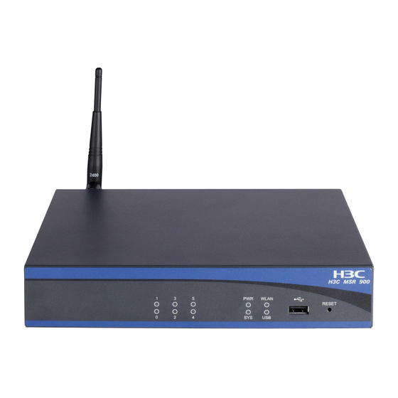
Page 6: Msr900-W Panel Views
MSR900-W panel views Figure 3 MSR900-W front panel (1) USB port (2) Reset button Figure 4 MSR900-W rear panel (1) Grounding screw (2) Console port (3) Ethernet WAN port ETH0 (4) Ethernet WAN port ETH1 (5) Ethernet LAN ports (ETH2 to ETH5) -
Page 7: Msr920 Panel Views
Figure 6 MSR900-W(NA) rear panel (1) Grounding screw (2) Console port (3) Ethernet WAN port ETH0 (4) Ethernet WAN port ETH1 (5) Ethernet LAN ports (ETH2 to ETH5) (6) Antenna port (7) Power adapter port MSR920 panel views Figure 7 MSR920 front panel... -
Page 8: Msr920-W Panel Views
MSR920-W panel views Figure 9 MSR920-W front panel (1) USB port (2) Reset button Figure 10 MSR920-W rear panel (1) Grounding screw (2) Antenna port (3) Console port (4) Ethernet WAN port ETH0 (5) Ethernet WAN port ETH1 (6) Ethernet LAN ports (ETH2 to ETH5) (7) Ethernet LAN ports (ETH6 to (8) Antenna port... - Page 9 Figure 12 MSR920-W(NA) rear panel (1) Grounding screw (2) Antenna port (3) Console port (4) Ethernet WAN port ETH0 (5) Ethernet WAN port ETH1 (6) Ethernet LAN ports (ETH2 to ETH5) (7) Ethernet LAN ports (ETH6 to (8) Antenna port (9) Power adapter port ETH9)
-
Page 10: Preparing For Installation
The power data for affected products—including the power consumption of the product in networked standby if all wired network ports are connected and all wireless network ports are activated—is provided in section P14, “Additional information,” of the product IT ECO Declaration available at http://www.hp.com/hpinfo/globalcitizenship/environment/productdata/iteconetworking.html. Site requirements The router can only be used indoors. -
Page 11: Emi
Table 3 Dust concentration limit in the equipment room Substance Concentration limit (particles/m ≤ 3 x 10 Dust particles (No visible dust on desk in three days) NOTE: Dust particle diameter ≥ 5 μm Table 4 Harmful gas concentration limits Max. -
Page 12: Installation Tools
Installation tools Accessories provided with the router Power cord • Console cable • Grounding cable • User-supplied tools and equipment Phillips screwdriver P1 – 100 mm, P2 – 150 mm and P3 – 250 mm • Plain screwdriver P4 – 75 mm •... - Page 13 Item Requirements Yes No • Keep the router far away from radio transmitters, radar, and high-frequency or high-voltage devices. • Use electromagnetic shielding when necessary. • The grounding cable of the chassis is grounded properly. • The grounding terminal of the AC power receptacle is grounded properly.
-
Page 14: Installing The Router
Installing the router WARNING! To avoid injury, do not touch bare wires, terminals, or parts with high-voltage hazard signs. This chapter provides instructions for installing the router on a workbench or mounting it in a 19-inch rack. Installation prerequisites You have read "Preparing for installation"... -
Page 15: Installing The Router
Figure 13 MSR900 router installation flowchart Installing the router When installing the router: • Reserve a space of 10 cm (3.9 in) around the router for heat dissipation. Do not place heavy objects on the router. • Installing the router on a workbench To install the router on a workbench, as shown in Figure... -
Page 16: Installing The Router On A Wall
Make sure the workbench is clean, stable, and properly grounded. Place the router upside down on the workbench and attach the rubber feet to the four round holes in the chassis bottom. Figure 14 Installing the router on a workbench Installing the router on a wall CAUTION: When mounting the router on a wall, position the router so the network interfaces face down (toward... -
Page 17: Grounding The Router
Figure 15 Wall-mounting the router 180 mm ≥ 22 mm ≥ 1.5 mm Grounding the router WARNING! Connecting the router grounding cable correctly is crucial for protecting the router from lightning and EMI. The grounding resistance should be less than 5 ohms. - Page 18 You can ground the router in one of the following ways, depending on the grounding conditions at the installation site: • Ground the router to a properly-grounded grounding strip. Ground the router to a grounding conductor buried in the earth. •...
-
Page 19: Installing An Antenna
Grounding the router to a buried grounding conductor If the installation site has no grounding strips but offers the option of grounding to earth, hammer a 0.5 m (1.64 ft) or longer angle iron or steel tube into the earth to serve as a grounding conductor, as shown in Figure Figure 18 Grounding to a conductor buried in the earth... - Page 20 For a 10/100 Mbps copper Ethernet port that supports MDI/MDIX autosensing, you can use either a straight-through cable or a crossover cable to connect the port to a hub or LAN switch. To connect an Ethernet cable: Connect one end of the cable to an Ethernet port on the router, as shown in Figure 20 Figure Connect the other end of the cable to the peer device.
-
Page 21: Connecting The Console Cable And Setting Terminal Parameters
Connecting the console cable and setting terminal parameters Connecting the console cable CAUTION: When using a console cable to connect a PC to the router, first connect the DB-9 end of the console cable to the PC serial port, and then connect the RJ-45 connector of the console cable to the router console port. - Page 22 Figure 23 The Connection Description interface of HyperTerminal In the Connect To dialog box (Figure 24) select the serial port to be used from the Connect using list, and then click OK. Figure 24 Selecting a port for the HyperTerminal connection In the Properties dialog box (Figure 25), set Bits per second to 9600, Data bits to 8, Parity to...
- Page 23 Figure 25 Setting serial port parameters In the HyperTerminal window (Figure 26), Select File > Properties. Figure 26 HyperTerminal window In the Test Properties dialog box (Figure 27), click the Settings tab, set the emulation to VT100 or Auto Detect, and click OK.
-
Page 24: Connecting The Power Adapter
Figure 27 Set the terminal emulation parameters Connecting the power adapter The router's power adapter converts AC power to DC power, as follows: • AC rated voltage range: 100 VAC to 240 VAC, 50 Hz to 60 Hz DC Rated voltage: 12 VDC •... -
Page 25: Verifying The Installation
Figure 28 Connect the power adapter (1) AC power cord (2) Power adapter (3) DC power receptacle Verifying the installation CAUTION: It post-installation check is important to ensure proper operation of the router. Before powering on the router, ensure that: There is enough space around the router for heat dissipation. - Page 26 System is starting... Do you want to check SDRAM? [Y/N] Booting Normal Extend BootWare..The Extend BootWare is self-decompressing..... Done! **************************************************************************** HP MSR900 BootWare, Version 2.24 **************************************************************************** Copyright (c) 2010-2011 Hewlett-Packard Development Company, L.P. Compiled Date : Feb 16 2011...
-
Page 27: Configuring Basic Settings For The Router
Configuring basic settings for the router After the router is powered on for the first time, configure basic settings for the router. For more information, see HP MSR Router Series Fundamentals Configuration Guide and HP MSR Router Series Fundamentals Command Reference. -
Page 28: Troubleshooting
• before returning a faulty router for service. The HP tamper-proof label attached to a mounting screw on the router chassis must be kept intact. • Before opening the chassis cover, contact HP Support for authorization; if you do not, you take full responsibility for all operation and maintenance failures. -
Page 29: Garbled Terminal Display
If you specify the simple keyword, the password is stored in plain text. You can use the display current-configuration command to view the password in the current configuration. After modifying the user password, save it by executing the save command. HP recommends saving the modifications as the default configuration file. -
Page 30: Super Password Loss
saved-configuration command to display the configuration, and then copying and executing the configuration. Super password loss The super password provides access to four super levels, enabling you to perform higher-level operations. To recover from super password loss: On the main BootWare menu, select 8. This setting (Clear Super Password) is valid only for the first reboot of the router. -
Page 31: Support And Other Resources
After registering, you will receive email notification of product enhancements, new driver versions, firmware updates, and other product resources. Related information Documents To find related documents, browse to the Manuals page of the HP Business Support Center website: http://www.hp.com/support/manuals For related documentation, navigate to the Networking section, and select a networking •... -
Page 32: Conventions
HP Education http://www.hp.com/learn • Conventions This section describes the conventions used in this documentation set. Command conventions Convention Description Boldface Bold text represents commands and keywords that you enter literally as shown. Italic Italic text represents arguments that you replace with actual values. - Page 33 Network topology icons Represents a generic network device, such as a router, switch, or firewall. Represents a routing-capable device, such as a router or Layer 3 switch. Represents a generic switch, such as a Layer 2 or Layer 3 switch, or a router that supports Layer 2 forwarding and other Layer 2 features.
-
Page 34: Appendix A Technical Specifications
Rated input voltage: 100 VAC to 240 VAC; 50 Hz or 60 Hz adapter Max AC 15 W power Operating 0°C to 45°C (32°F to 113°F) temperature Relative humidity (non- 5% to 90% condensing) NOTE: MSR900-W(NA) and MSR920-W(NA) are North American models. -
Page 35: Antenna Specifications
Antenna specifications Table 8 Antenna specification Item Specification Frequency range 2400 MHz to 2500 MHz Voltage Standing Wave Ratio ≤2.0 (VSWR) Input impedance 50 ohms Gain 2±1 dBi Max power consumption 25 W Input interface Reverse-polarity SMA-J Length 134 mm (5.28 in) Color Black Weight... -
Page 36: Appendix B Leds
Appendix B LEDs MSR900/MSR900-W/MSR900-W(NA) Table 9 MSR900/MSR900-W/MSR900-W(NA) LED description Location Status Description Steady green The power supply is connected. Front panel The power supply is not connected. Fast flashing The system is starting up. green Slow flashing The system is operating properly. -
Page 37: Msr920/Msr920-W/Msr920-W(Na)
MSR920/MSR920-W/MSR920-W(NA) Table 10 MSR920/MSR920-W/MSR920-W(NA) LED description Location Status Description Steady green The power supply is connected. Front panel The power supply is not connected. Fast flashing The system is starting up. green Slow flashing The system is operating properly. green Front panel Fast flashing A system problem has occurred. -
Page 38: Index
EMI (site requirements), troubleshooting no response from serial Ethernet port, connecting cable, chassis interface numbering, MSR900 panel views, MSR900-W panel views, MSR900-W(NA) panel views, failure (power supply), MSR920 panel views, MSR920-W panel views, garbled terminal display (troubleshooting), MSR920-W(NA) panel views, grounding... - Page 39 (troubleshooting no response), power LED off (troubleshooting), MSR900 technical specifications, power supply MSR900-W technical specifications, connecting Ethernet cable, MSR900-W(NA) technical specifications, connecting power adapter, MSR920 technical specifications, troubleshooting failure, MSR920-W technical specifications,...
- Page 40 (router installation), temperature, startup process, super password loss, technical specifications antenna, LED, MSR900, MSR900 LED, MSR900-W, MSR900-W LED, MSR900-W(NA), MSR900-W(NA) LED, MSR920, MSR920 LED, MSR920-W, MSR920-W LED, MSR920-W(NA), MSR920-W(NA) LED, terminal setting console parameters, system configuration problems,...
Need help?
Do you have a question about the MSR900-W and is the answer not in the manual?
Questions and answers