ADTRAN DDM+ H2TU-C Installation And Maintenance Manual
Hide thumbs
Also See for DDM+ H2TU-C:
- Installation and maintenance practice (68 pages) ,
- Quick manual (2 pages) ,
- Job aid (2 pages)
Table of Contents
Advertisement
Quick Links
CONTENTS
1.
GENERAL ........................................................................ 1
2.
INSTALLATION ............................................................. 2
3.
CONNECTIONS .............................................................. 3
4.
HDSL2 SYSTEM TESTING ........................................... 4
5.
FRONT PANEL OPERATION ...................................... 4
6.
CONTROL PORT OPERATION .................................... 7
7.
HDSL2 DEPLOYMENT GUIDELINES ....................... 18
8.
TROUBLESHOOTING PROCEDURES ...................... 19
9.
MAINTENANCE ........................................................... 19
10. PRODUCT SPECIFICATIONS ..................................... 19
11. WARRANTY AND CUSTOMER SERVICE ............... 19
Appendix A. HDSL2 Loopbacks ....................................... A-1
Appendix B. Shelf Configuration ....................................... B-1
FIGURES
ADTRAN DDM+ H2TU-C with Display ............ 1
H2TU-C Edge Connector Wiring ......................... 3
H2TU-C Span Powering Diagram ........................ 3
HDSL2 Loopbacks ................................................ 4
RS-232 (DB-9) Pin Assignments .......................... 7
HDSL2 Main Menu Screen ................................... 8
HDSL2 Unit Information Screen .......................... 9
Provisioning Screen .............................................. 9
Span Status Screen .............................................. 10
Figure 10. Detailed Status Screen ........................................ 10
Figure 11. Loopback and Test Commands Screen ............... 11
Screen .................................................................. 12
Screen .................................................................. 13
(Continued) .......................................................... 14
Figure 17. Circuit ID, Time/Date Screen ............................. 15
Figure 18. Terminal Modes Screen ...................................... 16
Figure 19. Alarm History Screen .......................................... 17
Figure 20. Event History Screen .......................................... 17
Figure 21. Deployment Guidelines ....................................... 18
TABLES
Faceplate Indicators ............................................... 2
Compliance Codes ................................................. 2
Status Condition and Alarm Messages .................. 5
Option Setting Parameters ..................................... 6
61222003L1-5A
DDM+ H2TU-C with Display
2-Wire HDSL (HDSL2)
Transceiver Unit for the Central Office
Installation and Maintenance
61222003L1-5, Issue 1
Trademarks: Any brand names and product names included in this document are
trademarks, registered trademarks, or trade names of their respective holders.
HDSL2 Loopback Options .................................... 7
Screen Abbreviations Defined ............................... 7
HDSL2 Loss Values ............................................. 18
Loop Insertion Loss Data ..................................... 18
Troubleshooting Guide ........................................ 19
Table 10. DDM+ H2TU-C Specifications ........................... 20
Table A-1. HDSL2 Loopback Control Codes ..................... A-2
Table A-2. In-Band Addressable Loopback Codes ............ A-3
MODE SELECT
H
D
S
L
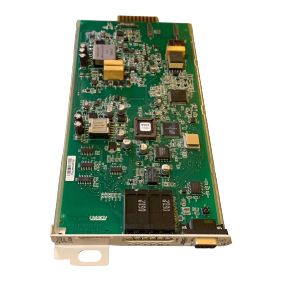
Figure 1. ADTRAN DDM+ H2TU-C with
Display
1. GENERAL
The ADTRAN DDM+ HDSL2 Transceiver Unit for
the Central Office (H2TU-C) with Display,
P/N 1222003L1, is the Central Office (CO) unit used
to deploy an HDSL2 T1 circuit using two-wire
metallic facilities. The unit occupies one slot in an
®
AT&T
DDM+ DS1 Extension shelf. The unit is
illustrated in Figure 1.
Revision History
This is the initial release of this document. Future
revisions to this document will be explained in this
subsection.
Section 61222003L1-5A
Issue 1, July 2001
CLEI # T1L3Y1BA _ _
1222003L1
STATUS
M
A
R
G
I
N
d
B
R
S
2
3
2
1
Advertisement
Table of Contents

Related Manuals for ADTRAN DDM+ H2TU-C


Summary of Contents for ADTRAN DDM+ H2TU-C
-
Page 1: Table Of Contents
CONNECTIONS .............. 3 Table 9. Troubleshooting Guide ........19 HDSL2 SYSTEM TESTING ........... 4 Table 10. DDM+ H2TU-C Specifications ......20 FRONT PANEL OPERATION ........4 Table A-1. HDSL2 Loopback Control Codes ..... A-2 CONTROL PORT OPERATION ........7 Table A-2. In-Band Addressable Loopback Codes .... A-3 HDSL2 DEPLOYMENT GUIDELINES ....... -
Page 2: Installation
The ADTRAN H2TU-C works in STATUS ..Blinking Red ..Signal Quality of 0 or No conjunction with the ADTRAN H2TU-R to provide a Sync on the HDSL2 loop DS1 service up to 12,000 feet on the local loop. -
Page 3: Connections
3. CONNECTIONS The DDM+ H2TU-C occupies one card slot in an AT&T DDM+ shelf. Power and alarm signals are provided to the card through the backplane of the shelf. DSX-1 and HDSL2 loop signals are connected to the wire-wrap pins or mass termination shelf connectors corresponding to the slot the unit occupies. -
Page 4: Hdsl2 System Testing
4. HDSL2 SYSTEM TESTING The ADTRAN HDSL2 system provides the ability to H2TU-C Network-Side Loopback monitor the status and performance of the DSX-1 LOCAL signals, DS1 signals, and HDSL2 loop signals. DSX-1 LOOP Detailed performance monitoring is provided by the... -
Page 5: Table 3. Status Condition And Alarm Messages
Provisioning, View, Default, and Loopback The display enters Status mode after power up or a Mode reset. It scrolls “ADTRAN HDSL2” and then The provisioning, view, default, or loopback mode is alternately displays loop margin for the HDSL2 loop, entered from the Status Mode after the MODE button any active alarm condition, and general status is acticated. -
Page 6: Table 4. Option Setting Parameters
The configuration parameters available in the Loopback Mode Provisioning Mode are described in Table 4. This mode selects and executes HDSL2 circuit loopbacks. Only one loopback may be active at a View Mode time. From the top level of the display, press the Select the VIEW mode to scroll through each option “MODE”... -
Page 7: Control Port Operation
This mode enables all screen highlighting and The screens illustrated in Figure 6 through Figure 23 cursor placement. Print screen and log file commands apply to an HDSL2 circuit deployed with ADTRAN’s are not available in this mode. HDSL2 technology. The circuit includes an H2TU-C The default terminal mode is Real Time Update. -
Page 8: Figure 6. Hdsl2 Main Menu Screen
5. Performance History 6. Circuit ID, Time/Date 7. Terminal Modes 8. Alarm History 9. Event History CIRCUIT ID: 01/01/00 00:03:05 Adtran HDSL2 Main Menu HDSL2 Unit Information Provisioning Span Status Loopbacks and Test Performance History Circuit ID, Time/Date Terminal Modes... -
Page 9: Figure 7. Hdsl2 Unit Information Screen
HDSL2 circuit. This screen HDSL2 circuit. To change a particular option setting, also displays contact information for ADTRAN select the appropriate number and a new menu will Technical Support, Internet site and address. -
Page 10: Figure 9. Span Status Screen
The Span Status Screen, illustrated in Figure 9, The Detailed Status selection from the Span Status provides quick access to status information for each Menu, illustrated in Figure 10, displays the HDSL2 HDSL2 receiver in the circuit. The legend selection and T1 status for each receiver point. -
Page 11: Figure 11. Loopback And Test Commands Screen
Figure 11 illustrates the Loopback and Test Commands Screen, which provides the user with the ability to evoke or terminate all available HDSL2 loopbacks. Each HDSL2 circuit component can be looped toward the network or customer from this screen. It also provides a self-test option to perform a self-diagnostic of the H2TU-C and H2TU-R. -
Page 12: Figure 12. 15-Minute Performance History Path Data Screen
The Performance History Screen, illustrated in Figure 48 hours worth of 60-minute interval data. At each 12, Figure 13, and Figure 14, displays the historical 24-hour interval, the performance data is transferred HDSL2 and T1 performance data in several different into the 24-hour performance data registers. -
Page 13: Figure 13. 60-Minute Performance History Line Data Screen
CIRCUIT ID: 01/01/00 00:07:07 Press ESC to return to precious menu Menu 60 Minute H2TUC DSX-1 Performance Data Definitions ES-L SES-L UAS-L PDVS-L B8ZS-L CV-L Reset Data 0001 0001 0000 0002 0427 00000 15 Min Data 01/01 00:00 1800 1800 1800 0000 0000... -
Page 14: Figure 15. Performance History Data Definitions Screen
Abbreviations used in the Performance History Screens are defined in Data Definitions Screens, see Figure 15 and Figure 16. CIRCUIT ID: 01/01/00 00:05:46 Press ESC to return to precious menu Performance Data Definitions H2TUC, H2TUR, and H2R LOOP Related: HDSL2 Framing ES-L Errored Seconds CRC>=1 or LOSW>=1... -
Page 15: Figure 17. Circuit Id, Time/Date Screen
Figure 17 illustrates the Circuit ID, Time/Date Screen. The circuit ID can be any alphanumeric string up to 25 characters in length. The date should be entered as MMDDYY (for example, enter January 02, 2000, as “010200”). The time should be entered using military time (for example, enter 3:15 p.m. -
Page 16: Figure 18. Terminal Modes Screen
This unit includes two terminal emulation modes. The By pressing the space bar 3 times the screen will be desired terminal mode can be selected from the refreshed and will reflect the most current circuit Terminal Modes Screen, illustrated in Figure 18. conditions and provisioning options. -
Page 17: Figure 19. Alarm History Screen
The Alarm History Screen, illustrated in Figure 19, The Event History Screen, illustrated in Figure 20, provides the user with a detailed alarm history and provides a log history of HDSL2 circuit events. events log for the HDSL2, T1 spans and the system alarm history. -
Page 18: Hdsl2 Deployment Guidelines
7. HDSL2 DEPLOYMENT GUIDELINES Loop loss per kft for other wire is summarized in Table 7. The ADTRAN HDSL2 system provides DS1-based services over loops designed to comply with the Table 7. HDSL2 Loss Values Carrier Service Area (CSA) guidelines given below. -
Page 19: Troubleshooting Procedures
Table 9 is a troubleshooting guide for the DDM+ H2TU-C. ADTRAN Sales Pricing and Availability 9. MAINTENANCE (800) 827-0807 The ADTRAN DDM+ H2TU-C requires no routine maintenance. ADTRAN Technical Support Pre-sales Applications/Post-sales Technical Assistance ADTRAN does not recommend that repairs be (800) 726-8663 performed in the field. -
Page 20: Table 10. Ddm+ H2Tu-C Specifications
DSX-1 Format ............Auto, SF, ESF, Unframed, FFFC (see footnote 1 on page 6) Power Tested with the ADTRAN H2R (P/N 1222045L1) and the ADTRAN H2TU-R (1222026L1). Total Power .............. -48 VDC @ 160 mA with H2TU-R HTU-C Power Dissipation ........4.0 watts with H2TU-R Span Power ............... -
Page 21: Appendix Ahdsl2 Loopbacks
Appendix A HDSL2 Loopbacks HDSL2 MAINTENANCE MODES The unit can detect the loopback activation or deactivation code sequence only if an error rate of This Appendix describes operation of the HDSL2 or better is present. system with regard to detection of in-band and ESF facility data link loopback codes. -
Page 22: Table A-1. Hdsl2 Loopback Control Codes
Table A-1. HDSL2 Loopback Control Codes A-2, A-3 Type Source Code Name Abbreviated .. (N) ..3in7 (1110000) ........... Loopback data from network toward network in the H2TU-R. (N) ..4in7 (1111000) ........... Loopback data from network toward network in the H2TU-C. (C) ... -
Page 23: Table A-2. In-Band Addressable Loopback Codes
Table A-2. In-Band Addressable Loopback Codes Function Code and Response Arm ..........11000 (also known as a 2-in-5 pattern) The H2TU-R will loop up toward the network. No AIS or errors will be sent as a result of this loopback. The H2TU-C will Arm. Disarm .......... - Page 24 Section 61222003L1-5, Issue 1 61222003L1-5A...
-
Page 25: Appendix B Shelf Configuration
Appendix B Shelf Configuration DDM Plus Shelf Population (Power Requirements) 1. Determine shelf fusing (A).................... _____ Amps Typically: 20 Amp for DDM Plus shelf (10 amp per side) 2. Divide (A) by 2 to provide 100 percent over current protection (B)......_____ Amps 3. - Page 26 Section 61222003L1-5, Issue 1 61222003L1-5A...
Need help?
Do you have a question about the DDM+ H2TU-C and is the answer not in the manual?
Questions and answers