Advertisement
Quick Links
Advertisement

Related Manuals for Deagostini Model Space H.M.S. Bounty Admiralty


Summary of Contents for Deagostini Model Space H.M.S. Bounty Admiralty
- Page 1 PACK 12...
- Page 2 PAGE PHASE The flagpole compartment Hatch 01 The deck’s details 01 1000 Hooks and rings 01 1002 1005 Rudder mounts 01 1009 Rudder mounts 02 Hatch 02 1013 1015 The deck’s details 02 1017 Hooks and rings 02 Design and production by Incipit srl Assembly guide edited by Milanoedit srl - www.milanoedit.com Published in Italy by De Agostini Publishing Italia S.p.A., 28100 Novara, Via G.
- Page 3 PAGE PHASE Hatch 03 1019 1021 Steps 01 1025 Hatch 04 Lifeboat supports 01 1029 Lifeboat supports 02 1033 1037 Steps 02 1040 Hooks and rings 03 Hooks and rings 04 1042 1045 Positioning the davits Design and production by Incipit srl Assembly guide edited by Milanoedit srl - www.milanoedit.com Published in Italy by De Agostini Publishing Italia S.p.A., 28100 Novara, Via G.
- Page 4 PAGE PHASE The bow hatches 1047 1049 The galley chimney 1057 The bell The deck’s details 03 1059 Crane and winch details 1061 1064 Positioning the pumps 1066 The hinges The winches 1068 1070 The bulwarks 16 Design and production by Incipit srl Assembly guide edited by Milanoedit srl - www.milanoedit.com Published in Italy by De Agostini Publishing Italia S.p.A., 28100 Novara, Via G.
- Page 5 PAGE PHASE The deck’s details 04 1074 1082 The vertical winch 1092 The bulwarks 17 The bulwarks’ details 01 1104 The bulwarks’ details 02 1111 1113 The bow’s details 01 1146 The rudder hinges The tiller 1150 1153 Positioning the cannons Design and production by Incipit srl Assembly guide edited by Milanoedit srl - www.milanoedit.com Published in Italy by De Agostini Publishing Italia S.p.A., 28100 Novara, Via G.
- Page 6 PAGE PHASE Positioning the rudder 1159 1163 Positioning the lanterns 1165 Positioning the lifeboat The first mast 1167 The second mast 1171 1177 The third mast 1183 The bow’s details 02 The deck’s details 05 1185 1188 The bow’s details 03 Design and production by Incipit srl Assembly guide edited by Milanoedit srl - www.milanoedit.com Published in Italy by De Agostini Publishing Italia S.p.A., 28100 Novara, Via G.
- Page 7 PAGE PHASE Positioning the anchors 1191 1199 Positioning the culverins 1203 The figurehead Design and production by Incipit srl Assembly guide edited by Milanoedit srl - www.milanoedit.com Published in Italy by De Agostini Publishing Italia S.p.A., 28100 Novara, Via G. da Verrazano 15 All rights reserved ©...
- Page 8 PACK 12 ASSEMBLY INSTRUCTIONS PACK 12 List of components wooden tablet 12-01 wooden tablet 12-07 wooden tablet 12-08 wooden tablet 12-02 wooden tablet 12-09 wooden tablet 12-03 wooden tablet 12-04 wooden tablet 12-05 1 figurehead wooden tablet 12-06 12-01 12-02 12-03 12-04 12-05...
- Page 9 PACK 12 PHASE 135 THE FLAGPOLE COMPARTMENT Detach the pieces shown from their tablets and join them together as shown, applying a drop of glue to the parts highlighted in red in the drawings.
- Page 10 PACK 12...
- Page 11 PACK 12...
- Page 12 PACK 12...
- Page 13 PACK 12...
- Page 14 PACK 12...
- Page 15 PACK 12...
- Page 16 PACK 12 Before joining the two C pieces to the rest of the group, paint them with Gun Metal.
- Page 17 PACK 12 Join the flagpole compartment to the rest of the model.
- Page 18 PACK 12...
- Page 19 PACK 12 PHASE 136 HATCH 01 Detach the pieces shown from tablet 12-07 and join them together as shown, applying a drop of glue to the parts highlighted in red in the drawings.
- Page 20 PACK 12...
- Page 21 PACK 12 PHASE 137 THE DECk’S DETAILS 01 13,5 Retrieve two of the parts of the flooring components left over from pack 10, and shape them as shown. Then join them to the assembly that you put together in Phase 136. 1000...
- Page 22 PACK 12 Join the assembly to the rest of the model, at the position shown. 1001...
- Page 23 PACK 12 PHASE 138 HOOkS AND RINGS 01 Drill 11 holes of 1mm diameter at the points marked in red. 1002...
- Page 24 PACK 12 Take the components shown above from the bag of detail items you received in pack 10. Paint the ring with Gun Metal, open it with pliers, and attach it to the hook; then close the ring. N.B.: repeat these operations whenever the instructions refer to “hooks with rings”. 1003...
- Page 25 PACK 12 Join 8 hooks, without rings, to the rest of the model, at the positions shown in red. Join 3 hooks with rings at the positions shown in green. 1004...
- Page 26 PACK 12 PHASE 139 RUDDER MOUNTS 01 Detach the pieces shown from their tablets and join them as shown, applying a drop of glue to the parts highlighted in the drawings. 1005...
- Page 27 PACK 12 Working on both sides of the support, remove the parts highlighted in red in the drawings. 1006...
- Page 28 PACK 12 Join the support to the rest of the model. 1007...
- Page 29 PACK 12 1008...
- Page 30 PACK 12 PHASE 140 RUDDER MOUNTS 02 Detach the pieces shown from their tablets and join them as shown, applying a drop of glue to the parts highlighted in the drawings. 1009...
- Page 31 PACK 12 Working on both sides of the support, remove the parts highlighted in red in the drawings. 1010...
- Page 32 PACK 12 Join the support to the rest of the model. 1011...
- Page 33 PACK 12 1012...
- Page 34 PACK 12 PHASE 141 HATCH 02 Detach the pieces shown from tablet 12-06 and join them together as shown, applying a drop of glue to the parts highlighted in red in the drawings. 1013...
- Page 35 PACK 12 1014...
- Page 36 PACK 12 PHASE 142 THE DECk’S DETAILS 02 Take two flooring components out of the bag of detail elements and shape them as shown. Then join them to the assembly that you put together in Phase 141. 1015...
- Page 37 PACK 12 Join the assembly to the rest of the model, at the position shown. 1016...
- Page 38 PACK 12 PHASE 143 HOOkS AND RINGS 02 Drill 8 holes of 1mm diameter at the points marked in red. 1017...
- Page 39 PACK 12 Join 4 hooks, without rings, to the rest of the model, at the positions shown in red. Join 4 hooks with rings at the positions shown in green. 1018...
- Page 40 PACK 12 PHASE 144 HATCH 03 Detach the pieces shown from tablet 12-08 and join them together as shown, applying a drop of glue to the parts highlighted in red in the drawings. 1019...
- Page 41 PACK 12 Join the assembly to the rest of the model. 1020...
- Page 42 PACK 12 PHASE 145 STEPS 01 Detach the pieces shown from tablet 12-01 and join them together as shown, applying a drop of glue to the parts highlighted in red in the drawings. 1021...
- Page 43 PACK 12 1022...
- Page 44 PACK 12 Take the ladder you have just assembled and joint it to the rest of the model, as shown. 1023...
- Page 45 PACK 12 1024...
- Page 46 PACK 12 PHASE 146 HATCH 04 Detach the pieces shown from tablet 12-08 and join them together as shown, applying a drop of glue to the parts highlighted in red in the drawings. 1025...
- Page 47 PACK 12 Using 1.5 x 6 x 250mm strips, make 7 equal Join the 7 parts together, as shown. parts, each 39mm long. Drill 2 x 1mm diameter holes in each part, as shown. Glue two strips to the ends of the assembly, as shown. The total length of the assembly must be 50mm. 1026...
- Page 48 PACK 12 Join together the two groups you have just assembled, as shown. 1027...
- Page 49 PACK 12 1028...
- Page 50 PACK 12 PHASE 147 LIFEBOAT SUPPORTS 01 Detach the SCP from tablet 12-07. Then join it to the assembly that you put together in Phase 146. 1029...
- Page 51 PACK 12 Insert 14 hooks with rings into the holes in the assembly. 1030...
- Page 52 PACK 12 Join the assembly to the rest of the model. 1031...
- Page 53 PACK 12 1032...
- Page 54 PACK 12 PHASE 148 LIFEBOAT SUPPORTS 02 Detach the pieces shown from their tablets and join them together as shown, applying a drop of glue to the parts highlighted in red in the drawings. 1033...
- Page 55 PACK 12 1034...
- Page 56 PACK 12 Join the assembly to the rest of the model. 1035...
- Page 57 PACK 12 1036...
- Page 58 PACK 12 PHASE 149 STEPS 02 Detach the pieces shown from tablet 12-01 and join them together as shown, applying a drop of glue to the parts highlighted in red in the drawings. 1037...
- Page 59 PACK 12 1038...
- Page 60 PACK 12 Take the ladder you have just assembled and joint it to the rest of the model. 1039...
- Page 61 PACK 12 PHASE 150 HOOkS AND RINGS 03 Drill 11 holes of 1mm diameter at the points marked in red. 1040...
- Page 62 PACK 12 Join 5 hooks, without rings, to the rest of the model, at the positions shown in red. Join 6 hooks with rings at the positions shown in green. 1041...
- Page 63 PACK 12 PHASE 151 HOOkS AND RINGS 04 Drill 6 holes of 1mm diameter at the points marked in red. 1042...
- Page 64 PACK 12 Join 7 hooks, without rings, to the rest of the model, at the positions shown in red. 1043...
- Page 65 PACK 12 Drill 4 x 0.5 mm diameter holes at the points marked in red. Paint 4 nails with Gun Metal and insert them into the holes you have just drilled. 1044...
- Page 66 PACK 12 PHASE 152 POSITIONING THE DAvITS Retrieve the two davits you assembled in pack 10 and attach them to the bow of the model, at the positions shown. 1045...
- Page 67 PACK 12 Drill 4 x 0.5mm diameter holes at the bases of the davits (two for each davit) at the positions shown. Paint 4 nails with Gun Metal and insert them into the holes you have just drilled. 1046...
- Page 68 PACK 12 PHASE 153 THE BOw HATCHES Detach the PPB and PPT pieces from tablet 12-05 and join them to the rest of the model, at the positions shown. 1047...
- Page 69 PACK 12 1048...
- Page 70 PACK 12 PHASE 154 THE GALLEY CHIMNEY Detach the parts shown from the photo-etching and shape them as shown. Then join them by applying a drop of glue and paint them with Gun Metal. 1049...
- Page 71 PACK 12 1050...
- Page 72 PACK 12 1051...
- Page 73 PACK 12 1052...
- Page 74 PACK 12 Detach the components shown above from their tablets. Glue them together and join the rest of the chimney. 1053...
- Page 75 PACK 12 1054...
- Page 76 PACK 12 Join the chimney to the rest of the model, at the positions shown. 1055...
- Page 77 PACK 12 1056...
- Page 78 PACK 12 PHASE 155 THE BELL Remove the SCM piece from the photo-etching and add it to the bell you received in pack 08. Paint the pieces with Gun Metal. 1057...
- Page 79 PACK 12 Join the group to the rest of the model, at the position shown. 1058...
- Page 80 PACK 12 PHASE 156 THE DECk’S DETAILS 03 Drill 2 x 3.5mm diameter holes at the positions shown. Shape as shown two segments of 1.5 x 6 x 250mm strip. 1059...
- Page 81 PACK 12 Join the details you have just shaped to the rest of the model. 1060...
- Page 82 PACK 12 PHASE 157 CRANE AND wINCH DETAILS Detach four G pieces from tablet 12-08 and shape them as shown. The other six G pieces will not be used. 1061...
- Page 83 PACK 12 Join two G pieces to the rest of the model, as shown. 1062...
- Page 84 PACK 12 Join other two G pieces to the model, at the positions shown. 1063...
- Page 85 PACK 12 PHASE 158 POSITIONING THE PUMPS Join the pumps that you assembled in the previous packs to the rest of the model, inserting them in the holes as shown. 1064...
- Page 86 PACK 12 1065...
- Page 87 PACK 12 PHASE 159 THE HINGES Detach two C pieces from the photo-etching and paint them with Gun Metal. Then join them to the rest of the model at the positions shown. 1066...
- Page 88 PACK 12 1067...
- Page 89 PACK 12 PHASE 160 THE wINCHES Take 4 winches from the bag of detail elements and glue them in at the holes highlighted in red; insert a 1mm diameter pin, 8mm long, into each hole. You can make the pins from a nail or using steel wire. 1068...
- Page 90 PACK 12 Carry out the same operations to join another 8 winches to the model, at the positions shown in the images. 1069...
- Page 91 PACK 12 PHASE 161 THE BULwARkS 16 Shape some 1,5 x 6 x 250mm strips as shown and join them to the rest of the model, at the positions shown. 1070...
- Page 92 PACK 12 1071...
- Page 93 PACK 12 Drill 1mm diameter holes, 2mm deep, at the positions shown. Then insert a hook into each hole (4 per side). 1072...
- Page 94 PACK 12 1073...
- Page 95 PACK 12 PHASE 162 THE DECk’S DETAILS 04 Detach K parts from tablet 12-08 and join to the rest of the model, as shown. 1074...
- Page 96 PACK 12 1075...
- Page 97 PACK 12 Detach the parts shown from tablet 12-04 and join them together as shown in the instructions. 1076...
- Page 98 PACK 12 1077...
- Page 99 PACK 12 1078...
- Page 100 PACK 12 1079...
- Page 101 PACK 12 1080...
- Page 102 PACK 12 Join the assembly to the rest of the model. 1081...
- Page 103 PACK 12 PHASE 163 THE vERTICAL wINCH The illustrations on these pages show how to assemble the vertical winch. Then join it to the rest of the model, at the position shown. 1082...
- Page 104 PACK 12 1083...
- Page 105 PACK 12 1084...
- Page 106 PACK 12 1085...
- Page 107 PACK 12 1086...
- Page 108 PACK 12 1087...
- Page 109 PACK 12 1088...
- Page 110 PACK 12 1089...
- Page 111 PACK 12 1090...
- Page 112 PACK 12 1091...
- Page 113 PACK 12 PHASE 164 THE BULwARkS 17 Detach the components shown from tablet 12-02 and join them to the rest of the model at the positions shown. 1092...
- Page 114 PACK 12 1093...
- Page 115 PACK 12 1094...
- Page 116 PACK 12 PB1-PB2 Detach the components shown from tablet 12-07, assemble them as shown and join them to the rest of the model. 1095...
- Page 117 PACK 12 PB3-PB4 1096...
- Page 118 PACK 12 PB5-PB6 1097...
- Page 119 PACK 12 PB1-PB2 PB3-PB4 PB5-PB6 1098...
- Page 120 PACK 12 PT1-PT2 Detach the components shown from tablet 12-06, assemble them as shown and join them to the rest of the model. 1099...
- Page 121 PACK 12 PT3-PT4 1100...
- Page 122 PACK 12 PT5-PT6 1101...
- Page 123 PACK 12 PT1-PT2 PT3-PT4 PT5-PT6 1102...
- Page 124 PACK 12 1103...
- Page 125 PACK 12 PHASE 165 THE BULwARkS’ DETAILS 01 Take the components shown from the bag of detail elements (distinguishable from the others because they are smaller in size), paint the rings with Gun Metal, and join the pieces together. Repeat the same operations with the larger items. 1104...
- Page 126 PACK 12 Join 3 of the details with the smaller elements to the rest of the model, as shown. 1105...
- Page 127 PACK 12 Detach the L components from the photo-etching, take the long rings out of the bag, and paint them with Gun Metal. Open the rings with pliers and join the components to the details you just installed on the model; after joining them, close the rings.
- Page 128 PACK 12 Insert 2 nails for each detail into the holes as shown. 1107...
- Page 129 PACK 12 Insert 1 small detail and 5 large details in the positions shown. Then repeat these operations for steps 4-6. 1108...
- Page 130 PACK 12 Insert 1 small detail and 5 large details in the positions shown. Then repeat these operations for steps 4-6. 1109...
- Page 131 PACK 12 1110...
- Page 132 PACK 12 PHASE 166 THE BULwARkS’ DETAILS 02 Detach eight GR pieces from tablet 12-02 and join them to your model at the positions shown. 1111...
- Page 133 PACK 12 Repeat the same operation with other two GR pieces. 1112...
- Page 134 PACK 12 PHASE 167 THE BOw’S DETAILS 01 Using a file, enlarge the hole that already exists at the position shown above, until you obtain the size shown. 1113...
- Page 135 PACK 12 1114...
- Page 136 PACK 12 SST1 SSB1 SGT1 SGB1 SGT2 SGB2 SST2 SSB2 SGT1 Remove the pieces shown from their tablets and join them to the bow of the model as shown in the instructions on these pages. 1115...
- Page 137 PACK 12 Shape the component as shown, if needed. 1116...
- Page 138 PACK 12 SST1 SSB1 SGT1 SGB1 SGT2 SGB2 SST2 SSB2 SGT2 1117...
- Page 139 PACK 12 SGT2 1118...
- Page 140 PACK 12 SST1 SSB1 SGT1 SGB1 SGT2 SGB2 SST2 SSB2 SST1 1119...
- Page 141 PACK 12 1120...
- Page 142 PACK 12 SST1 SSB1 SGT1 SGB1 SGT2 SGB2 SST2 SSB2 SST2 1121...
- Page 143 PACK 12 SST2 1122...
- Page 144 PACK 12 SST1 SSB1 SGT1 SGB1 SGT2 SGB2 SST2 SSB2 1123...
- Page 145 PACK 12 Before joining it to the model, paint the component with Gun Metal. 1124...
- Page 146 PACK 12 SST1 SSB1 SGT1 SGB1 SGT2 SGB2 SST2 SSB2 1125...
- Page 147 PACK 12 1126...
- Page 148 PACK 12 SST1 SSB1 SGT1 SGB1 SGT2 SGB2 SST2 SSB2 SGB1 1127...
- Page 149 PACK 12 SGB1 1128...
- Page 150 PACK 12 SST1 SSB1 SGT1 SGB1 SGT2 SGB2 SST2 SSB2 SGB2 1129...
- Page 151 PACK 12 SGB2 1130...
- Page 152 PACK 12 SST1 SSB1 SGT1 SGB1 SGT2 SGB2 SST2 SSB2 SSB1 1131...
- Page 153 PACK 12 SSB1 1132...
- Page 154 PACK 12 SST1 SSB1 SGT1 SGB1 SGT2 SGB2 SST2 SSB2 1133...
- Page 155 PACK 12 SSB2 1134...
- Page 156 PACK 12 SST1 SSB1 SGT1 SGB1 SGT2 SGB2 SST2 SSB2 1135...
- Page 157 PACK 12 Before joining it to the model, paint the component with Gun Metal. 1136...
- Page 158 PACK 12 SST1 SSB1 SGT1 SGB1 SGT2 SGB2 SST2 SSB2 1137...
- Page 159 PACK 12 1138...
- Page 160 PACK 12 Drill two 0.5mm diameter holes at the positions shown and insert a nail into each hole. 1139...
- Page 161 PACK 12 1140...
- Page 162 PACK 12 1141...
- Page 163 PACK 12 1142...
- Page 164 PACK 12 1143...
- Page 165 PACK 12 1144...
- Page 166 PACK 12 Paint with Gun Metal the inner parts of the STS, STG, SBS and SBG pieces. 1145...
- Page 167 PACK 12 PHASE 168 THE RUDDER HINGES Detach four TM4 pieces from the photo-etching and shape them as shown. 1146...
- Page 168 PACK 12 Shape 4 nails as shown, fit them into the hinges, and then join the assemblies to the rudder, at the positions shown. 1147...
- Page 169 PACK 12 Repeat the same operations with the four TM5 pieces of the photo-etching. 1148...
- Page 170 PACK 12 Join the four TM5 pieces to the stern of the model and join the rudder as shown. 1149...
- Page 171 PACK 12 PHASE 169 THE TILLER Detach the BT piece from tablet 8-10 and drill 2 x 1mm diameter holes. Insert 4 hooks into the holes (2 per side). 1150...
- Page 172 PACK 12 Join the BT piece to the rest of the model, as shown. 1151...
- Page 173 PACK 12 1152...
- Page 174 PACK 12 PHASE 170 POSITIONING THE CANNONS Take the cannons you assembled in the previous packs. Drill two 1mm diameter holes at the positions shown and insert 1 hook into each hole. 1153...
- Page 175 PACK 12 Paint the inner parts of all the wheels with Gun Metal. Place the cannons on the model, as shown. 1154...
- Page 176 PACK 12 Take the components shown out of the bag and combine them as shown. Do this until you have obtained 8 “simple” elements. 1155...
- Page 177 PACK 12 Take the components shown out of the bag and combine them as shown. Do this until you have obtained 8 “double” elements. Place the elements as shown. Repeat the same operation on the other side of the gun carriage. 1156...
- Page 178 PACK 12 As shown, attach the 0.25mm rope, which you will find in the bag of detail elements. Repeat the operation on the other side of the cannon, for all cannons. 1157...
- Page 179 PACK 12 Repeat the operations of steps 8-10 on the other cannons. Ripete l'operazione di trincatura 1158 per tutti e 4...
- Page 180 PACK 12 PHASE 171 POSITIONING THE RUDDER Take an 8mm diameter shaft and cut it as shown. Join it to the helm, which you will find in the bag of detail elements. Place the assembly at the position shown. 1159...
- Page 181 PACK 12 1160...
- Page 182 PACK 12 Take the components shown out of the bag and combine them as shown. Do this until you have obtained 10 “simple” elements. Join the simple elements to the hooks as shown above. 1161...
- Page 183 PACK 12 Using a 0.5mm rope, carry out the sequence as shown. 1162...
- Page 184 PACK 12 PHASE 172 POSITIONING THE LANTERNS Drill 4 blind holes at the positions shown above. Then take the lanterns that you assembled in pack 09, paint them with Gun Metal, and add them to the stern of the model, as shown. 1163...
- Page 185 PACK 12 1164...
- Page 186 PACK 12 PHASE 173 POSITIONING THE LIFEBOAT Join the lifeboat, which you assembled in pack 09, to the rest of the model. 1165...
- Page 187 PACK 12 Secure the lifeboat in place with two 0.5mm ropes. 1166...
- Page 188 PACK 12 PHASE 174 THE FIRST MAST Take a 6mm diameter mast and shape it as shown. 1167...
- Page 189 PACK 12 10° Detach the CT piece from tablet 7-06 and shape it as shown. Then join the component and the mast to the rest of the model, at the position shown. 1168...
- Page 190 PACK 12 1169...
- Page 191 PACK 12 1170...
- Page 192 PACK 12 PHASE 175 THE SECOND MAST Take a 10mm diameter mast and shape it as shown. 1171...
- Page 193 PACK 12 Detach the 6 components M from the photo-etching, paint them with Gun Metal and shape them as shown. 1172...
- Page 194 PACK 12 Join the M pieces to the second mast at the positions shown. 1173...
- Page 195 PACK 12 10° Detach the CM piece from tablet 7-06 and shape it as shown. Then join the component and the second mast to the rest of the model at the position shown. 1174...
- Page 196 PACK 12 1175...
- Page 197 PACK 12 1176...
- Page 198 PACK 12 PHASE 176 THE THIRD MAST Take a 8mm diameter mast and shape it as shown. 1177...
- Page 199 PACK 12 Detach the 5 components T from the photo-etching, paint them with Gun Metal and shape them as shown. 1178...
- Page 200 PACK 12 Join the T pieces to the third mast at the positions shown. 1179...
- Page 201 PACK 12 10° Detach the CP piece from tablet 7-06 and shape it as shown. Then join the component and the third mast to the rest of the model, at the position shown. 1180...
- Page 202 PACK 12 1181...
- Page 203 PACK 12 1182...
- Page 204 PACK 12 PHASE 177 THE BOw’S DETAILS 02 Take a 8mm diameter rod and shape it as shown. 1183...
- Page 205 PACK 12 Using a round file, work the pieces highlighted in green to make it easier to insert the rod. Then join the rod to the bow of the model. 1184...
- Page 206 PACK 12 PHASE 178 THE DECk’S DETAILS 05 Take the items shown from the bag and fit them into the holes as shown. The number of components to be used at each step is shown in the relative illustration. 1185...
- Page 207 PACK 12 1186...
- Page 208 PACK 12 1187...
- Page 209 PACK 12 PHASE 179 THE BOw’S DETAILS 03 As shown, attach a 0.5mm rope. 1188...
- Page 210 PACK 12 Wind the rope 7 times. 1189...
- Page 211 PACK 12 Continue winding horizontally. Continue upwards for 11 turns of the rope. 1190...
- Page 212 PACK 12 PHASE 180 POSITIONING THE ANCHORS Retrieve the anchors that you assembled in the previous packs. Take two large rings from the bag, attach them to the anchors, and wrap a 0.25mm rope around each as shown. 1191...
- Page 213 PACK 12 Place the first anchor at the position shown and secure it in place using a 0.25mm rope. 1192...
- Page 214 PACK 12 Detach two G components from the photo-etching and join them to two of the components shown above (contained in the bag). 1193...
- Page 215 PACK 12 Take the component you have just made and join it to the anchor. Attach the pieces together using a 0.5mm rope, as shown in the drawing. Wind the rope on the components as shown. 1194...
- Page 216 PACK 12 Repeat steps 2-5 to place the second anchor. Ripete le stesse operazioni per il lato di babordo. 1195...
- Page 217 PACK 12 Using a 2mm rope, carry out the sequence as shown. 1196...
- Page 218 PACK 12 Wind a 0.25mm rope at the position shown. 1197...
- Page 219 PACK 12 Repeat steps 7-8 on the other anchor. 1198...
- Page 220 PACK 12 PHASE 181 POSITIONING THE CULvERINS Take the culverins that you assembled in the previous packs and fit them into the holes highlighted in the drawings. 1199...
- Page 221 PACK 12 1200...
- Page 222 PACK 12 1201...
- Page 223 PACK 12 1202...
- Page 224 PACK 12 1203...
- Page 225 PACK 12 PHASE 182 THE FIGUREHEAD Paint the figurehead as shown in the photographs: flesh colour for the face and hands, yellow for the hair, white, red and dark blue for the clothing, and black for the cape, hat and shoes. Try to position the figurehead at the position shown;...
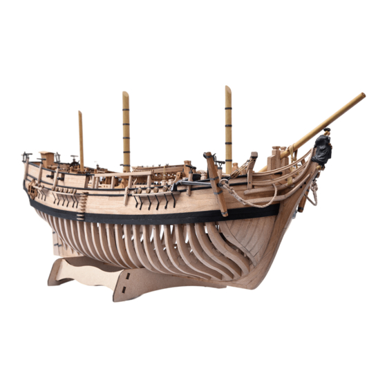
- Page 226 PACK 12 Now that you have added this important component, your flagship Bounty model is finally complete. On the following pages you will be able to admire some general views and numerous details of your model. 1205...
- Page 227 PACK 12 1206...
- Page 228 PACK 12 1207...
- Page 229 PACK 12 1208...
- Page 230 PACK 12 1209...
- Page 231 PACK 12 1210...
- Page 232 PACK 12 1211...
- Page 233 PACK 12 1212...
- Page 234 PACK 12 1213...
Need help?
Do you have a question about the Model Space H.M.S. Bounty Admiralty and is the answer not in the manual?
Questions and answers