
Related Manuals for Deagostini Model Space HUMMER H1


Summary of Contents for Deagostini Model Space HUMMER H1
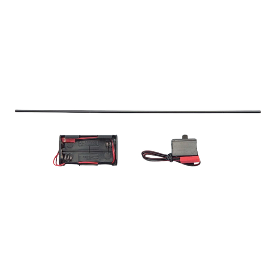
- Page 1 HUMMER H1: STEP BY STEP ™ Stage 45 The battery box and power switch – an overview Your parts Aerial tube Battery box Power switch...
- Page 2 HUMMER H1: STEP BY STEP ™ The power switch and battery box The battery box and power switch is located inside the radio box, which The power supply in your Hummer H1 uses alkaline AA will be fitted to the base of the chassis in coming stages. The box is batteries.
- Page 3 HUMMER H1: STEP BY STEP ™ Stage 46 Mounting the radio box Your parts Radio box upper and lower (temporarily assembled) 3 × 3mm set screws x 3 Throttle spring Radio box lid (temporarily assembled) Body pins × 2 2mm stoppers × 2 3 ×...
- Page 4 HUMMER H1: STEP BY STEP ™ Remove the cellophane tape holding together the parts that Lay out the parts and make a note of which is which. To the make up the radio box. bottom left (1) is the box upper, at the top is the box lower (2) and to the bottom right (3) is the lid.
- Page 5 HUMMER H1: STEP BY STEP ™ Next, fit and tighten the second 3 × 8mm Place the 3 × 10mm self-tapping screw into Fit the remaining 3 × 8mm self-tapping self-tapping screw into the adjacent hole. the hole that sits on the joint between the screws into the last three holes that were chassis’s main and rear plates.
- Page 6 HUMMER H1: STEP BY STEP ™ Stage 47 Installing the steering servo Your parts Steering servo (KS-302DS) Servo horn 2.6 × 10mm servo horn screw Philllips screwdriver Steering rod (Stage 46) Tools and Needle-nose pliers 3 × 10mm self-tapping screws × 4 (Stage 46) 1.5mm Allen key (Stage 11) 3 ×...
- Page 7 HUMMER H1: STEP BY STEP ™ Hold the radio box upper so that its underside is facing up, then place the steering servo into the rectangular space so that the screw holes on both parts line up. Prepare the above parts saved from Stage 46. Lay out the steering rod, four 3 ×...
- Page 8 HUMMER H1: STEP BY STEP ™ Wrap the steering rod Hold the steering rod (Stage 46) in a strip of firmly in the needle-nose paper towel or tissue to pliers, then insert its tip protect it. into the circled hole on the servo horn, as shown.
- Page 9 HUMMER H1: STEP BY STEP ™ Hold the servo horn Hold the steering box steady, and move the with the steering servo steering rod back and facing upwards, as shown. Place the steering rod and forth a number of times. This is to very slightly servo horn assembly onto widen the hole and create...
- Page 10 HUMMER H1: STEP BY STEP ™ Carefully lower the radio Inspect the photo box (upper) onto the carefully. The steering rod lower section fitted in the should be almost straight, previous stage. The parts with the steering servo at should fit together snugly. right angles to the edge of the radio box.
-
Page 11: Tools And Materials
HUMMER H1: STEP BY STEP ™ Stage 48 Fitting the throttle servo Your parts Throttle servo (KS-302DS) Servo horn Servo horn screw Phillips screwdriver Paper towel or tissue Needle-nose pliers (two pairs) Thread-locking agent or Tools and Cutters rubber-based adhesive Scissors Silicon tubing (Stage 43) materials... - Page 12 HUMMER H1: STEP BY STEP ™ Hold the throttle linkage rod (Stage 46) with the needle-nose pliers, covering it with a piece of folded paper towel or tissue for protection. Screw the throttle ball end (also Stage 46) onto the threaded tip.
- Page 13 HUMMER H1: STEP BY STEP ™ Place a 2mm washer over Making sure the washer the protruding tip of the and screw do not fall out, screw at the other side of place the tip of the screw the linkage base. into the circled hole on the side of the servo horn.
- Page 14 HUMMER H1: STEP BY STEP ™ Slide one of the lengths Slide the tube along until of silicon tubing over the it rest against the side of free end of the throttle the linkage base. linkage rod. Place the first 3 × 3mm Turn the set screw set screw (Stage 46) into the hole, but stop...
- Page 15 HUMMER H1: STEP BY STEP ™ Very carefully remove the Hold the radio box top temporarily-fixed radio with its underside facing box top from the chassis upwards, with the throttle assembly (Stage 47). To servo in your other hand, do this, you will need to with the circular output unscrew the set screw shaft at the top of the box.
- Page 16 HUMMER H1: STEP BY STEP ™ Place a 3 × 10mm binding- Tighten the screw gently head self-tapping screw with a screwdriver. into the first of the holes along the edge of the radio box. Tighten each of the Carefully re-insert the remaining five screws into steering rod into the front the remaining holes lining...
- Page 17 HUMMER H1: STEP BY STEP ™ Place the servo horn screw into the With the brake rod still attached through Push the servo horn down so that it slots central hole of the servo horn, then into place, with the output shaft on the top the brake lever, place the throttle servo tighten with a screwdriver.
- Page 18 HUMMER H1: STEP BY STEP ™ After Before Hold the first of the two body pins Hold the circular end of the body pin in the The photo shows the correct angle of the supplied with Stage 46 in the needle-nose second pair of pliers, then very carefully bend in the body pin.
Need help?
Do you have a question about the Model Space HUMMER H1 and is the answer not in the manual?
Questions and answers