Table of Contents
Advertisement
Advertisement
Table of Contents

Related Manuals for Star Micronics TSP743II Series


Summary of Contents for Star Micronics TSP743II Series
- Page 1 THERMAL PRINTER 700 II SERIES Hardware Manual...
- Page 2 Federal Communications Commission Radio Frequency Interference Statement This device complies with Part 15 of FCC Rules and Industry Canada licence-exempt RSS standard(s). Operation is subject to the following two conditions: (1) This device may not cause harmful interference, and (2) this device must accept any interference received, including interference that may cause undesired operation. Le présent appareil est conforme aux CNR d'Industrie Canada applicables aux appareils radio exempts de licence.
- Page 3 • IOS is a trademark or registered trademark of Cisco in the U.S. and other countries and is used under license. • Android is a trademark of Google Inc. • Windows is registered trademarks of Microsoft Corporation. • Bluetooth® wordmark and logo are registered trademarks owned by Bluetooth SIG, Inc. Copyright © 2007-2017 Star Micronics Co., Ltd..
-
Page 4: Table Of Contents
TABLE OF CONTENTS 1. Unpacking and Installation ................. 5 1-1. Unpacking ....................5 1-2. Notes about Installation ................5 2. Parts Identification and Nomenclature ............... 6 3. Setup ........................7 3-1. Connecting the Interface Cable to the PC ..........7 3-2. -
Page 5: Unpacking And Installation
1. Unpacking and Installation 1-1. Unpacking After unpacking the unit, check that all the necessary accessories are included in the package. Printer Cable cover Holding plate Screws Roll stoppers Paper roll Shaft Switch blind Setup sheets Note: The ferrite core and fastener provided with your printer depend on your printer configuration. -
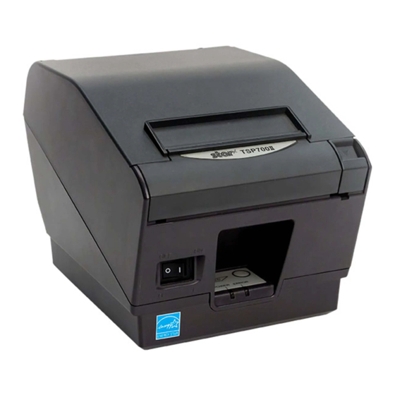
Page 6: Parts Identification And Nomenclature
2. Parts Identification and Nomenclature Printer cover Open this cover to load or replace paper. Power switch Used to turn on/ off power to the printer. Control panel Cover open lever Features LED indicators to indi- Push this lever in the direction of the ar- cate printer status and switches row to open the printer cover. -
Page 7: Setup
3. Setup 3-1. Connecting the Interface Cable to the PC 3-1-1. Parallel Cable Connect the parallel cable to a parallel port on your PC. 3-1-2. RS-232C Cable Connect the RS-232C cable to a RS-232C port on your PC. 3-1-3. USB Cable Connect the USB cable to a USB port on your PC. -
Page 8: Connecting The Interface Cable To The Printer
3-2. Connecting the Interface Cable to the Printer Printer cables are not included in the package. Obtain an appropriate cable that complies with the specifications beforehand. Because the appropriate interface cable differs depending on the system that you are connecting the printer to, contact the dealer that you bought the product from if you are unsure about what cable to use. - Page 9 3-2-2. RS-232C Interface Cable (1) Make sure that the AC adapter’s power cord is not connected to the outlet. (2) Connect the interface cable to the connector on the rear panel of the printer. (3) Tighten the connector screws. RS-232C interface cable 3-2-3.
- Page 10 3-2-4. Ethernet Cable If a ferrite core is included, install the ferrite core onto the Ethernet cable according to the following procedure to prevent electrical noise. If a ferrite core is not included, perform steps (1) and (5) only. When using an Ethernet cable that is 10 cm or less, shielded cable is recommended. (1) Make sure the printer is turned off.
-
Page 11: Connecting The Ac Adapter
3-3. Connecting the AC Adapter Note: Before connecting or disconnecting the AC adapter, make sure that the printer and all the devices connected to it are turned off. Then remove the power cord from the outlet. (1) Connect the AC adapter to the power cord. (2) Connect the AC adapter to the connector on the printer. -
Page 12: Turning The Power On
3-4. Turning the Power On Connect the power cord according to the procedure in section 3-3, “Connecting the AC Adapter”. Turn on the power switch, which is on the front side of the printer. The POWER lamp on the control panel will light. Power switch 3-5. -
Page 13: Loading A Paper Roll
3-6. Loading a Paper Roll Use a paper roll that complies with the printer specifications. (1) Push the cover open lever, and open the printer cover. Cover open lever (2) If the thickness of the paper is 65 to 99 µm, install the tension bar on the printer as shown. If the thickness of the paper is 100 to 150 µm, it is not necessary to install the tension bar. - Page 14 (5) Load the paper roll into the printer in the direction indicated by the figure, and pull the leading edge of the paper straight toward you. Paper roll Note: Make sure not to pass the paper under the tension bar. In the following condition, remove the tension bar unit and change the adjustment lever position in accordance with the procedures described in paragraphs 3-6-2 and 3-6-3: * Paper thickness between 100 μm and 150 μm, or paper width of 57.5 mm on the vertical/wall-mount layout.
- Page 15 3-6-1. Compliant Paper Roll Specifications 65 to 75 μm: f 18±1mm(Core outer), f 18±1mm(Core outer) Paper thickness 65 to 75 μm: f 32±1mm(Core outer), f 25.4±1mm(Core outer) Thermal Paper 75 to 150 μm: f 32±1mm(Core outer), f 25.4±1mm(Core outer) Thermal Label Paper Max.150 μm 79.5 ±...
- Page 16 3-6-3. Changing the Adjustment Lever Position The adjustment lever position must be changed in accordance with the paper thickness. It is factory-set to position 1. When using paper thickness between 100 and 150 μm, change the adjustment lever position in accordance with the procedure below.
-
Page 17: Bluetooth Settings (For Bluetooth Interface Models Only )
Device name: Star Micronics (default) (4) In an iOS device, after pairing, the LED will automatically begin flashing blue, and the printer will be automatically connected. - Page 18 Enter the following information in the master device if it does not support SSP, or when otherwise necessary. PIN: 1234 (default) Device name: Star Micronics (default) It is recommended that you change the PIN code for greater security. For details regard changing the PIN code, please see the “Software Manual -Star Bluetooth Utility- ”.
- Page 19 See the table below for details of Auto Connection setting. Auto Connection ON Auto Connection OFF Reconnecting without changing After the printer is turned on, it After turning on the printer, tap automatically connects to the last this printer's name on the Blue- the master device master device that was connected.
- Page 20 3-7-4. Setting up Auto Connection uSetting up from the Main Unit for the TSP700II Note : The following procedure explains how to change the Auto Connection function setting from ON to OFF. If you want to change it from OFF to ON, please follow the same procedure. (1) When paper is loaded in the printer and it is turned on, the [POWER] LED(green) on the front of the printer turns on.
- Page 21 3-7-5. Resetting Bluetooth Settings The following procedure explains how to initialize settings that you have changed such as the PIN code, device name, and so on. (1) While inserting a thin object such as the tip of a pen and holding down the RST button on the rear of the printer, turn on the printer's power switch.
-
Page 22: Setup Precautions
3-8. Setup Precautions Caution Symbol These symbols are located near the thermal print head. Because the thermal print head is hot immediately after printing, do not touch it. Static electricity can damage the thermal print head. To protect the thermal print head from static electricity, do not touch it. - Page 23 Below is a list of laws this device has been approved by. As Star Micronics is committed to constant innovation, revi- sions may be made without an announcement. Access the Star Micronics website for the latest listing of approvals.
-
Page 24: Attaching The Accessories
4. Attaching the Accessories The following accessories are necessary when mounting the printer to a wall. • Holder plate and two flangeless screws The following accessories do not necessarily have to be attached. Attach it if necessary. • Cable cover •... - Page 25 (3) Use a regular screwdriver to remove the clips at both ends of the bar to remove the tension bar unit. Note: If the paper witdth is 79.5 or 82.5mm and the paper thickness is less than 100μm, you do not need to remove the tension bar unit�...
- Page 26 Precautions regarding installation CAUTION This caution indicates information that, if ignored, could lead to personal injury or property damage. • Be sure to have qualified personnel install the specified screws and printer to the wall. Star is not responsible for any accidents or injuries that occur as a result of improper installation, misuse, or modifications.
-
Page 27: Attaching The Cable
4-2. Attaching the Cable Attach the cable cover as shown in the illustration. 4-3. Switch Blind Installation It is not necessary to install the switch blind. Only install it if it is necessary for you. By installing the switch blind, the following become possible. -
Page 28: Error Indicators
5. Error Indicators 5-1. Recoverable errors Check the recovery conditions. The printer can be recovered while maintaining its current status. Error description POWER ERROR Recovery condition Thermal head high Flashes at 0.5 sec- The printer recovers automatically when the thermal head temperature detection error ond intervals cools. -
Page 29: Preventing And Clearing Paper Jams
6. Preventing and Clearing Paper Jams 6-1. Preventing Paper Jams The paper should not be touched during ejection and before it is cut. Pressing or pulling the paper during ejection may cause a paper jam, paper cutting failure or line feed failure. 6-2. -
Page 30: Maintenance
7. Maintenance Accumulation of paper dust and dirt may cause the printer to not print portions of characters. To prevent such problems, perform periodic maintenance, such as removing paper dust from the paper transport sec- tion and removing the blackened paper dust from the thermal head surface. As a guideline, clean the printer every six months. - Page 31 1999/5/CE. [Estonian] Wireless Device vastavust direktiivi 1999/5/EÜ põhinõuetele Hrvatski : Ovime Star Micronics CO., LTD. Izjavljuje da je bežični uređaj ja nimetatud direktiivist tulenevatele teistele asjakohastele u skladu s osnovnim zahtjevima i drugim važnim odredbama [Croatian] sätetele.
- Page 32 Manufacturer’s Name Star Micronics Co.,Ltd. Manufacturer’s Address 20-10 Nakayoshida, Suruga-ku, Shizuoka-shi, Shizuoka 422-8654 Japan Importer’s Name Star Micronics Europe Ltd. Importer’s Address Star House, Peregrine Business Park, Gomm Road, High Wycombe, Bucks. HP13 7DL, U.K. Type of Equipment Thermal Printer...
- Page 33 URL: http://www.star-m.jp/eng Rev. 1.8...
Need help?
Do you have a question about the TSP743II Series and is the answer not in the manual?
Questions and answers