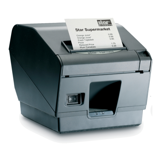
Star Micronics TSP700 Series Product Specifications
Hide thumbs
Also See for TSP700 Series:
- User manual (116 pages) ,
- Programmer's manual (116 pages) ,
- Technical manual (43 pages)

Related Manuals for Star Micronics TSP700 Series


Summary of Contents for Star Micronics TSP700 Series
-
Page 1: Product Specifications
Product Specifications TSP700 Series Rev. No. 2.10 Star Micronics Co., Ltd. Special Products Operating Division... - Page 2 Table of Contents G E N E R A L D E S C R I P T I O N ..............1 - 1 B A S I C S P E C I F I C A T I O N S .
- Page 3 O P E R A T I O N P A N E L A N D F U N C T I O N S ..........1 3 - 1 1 3 .
-
Page 4: General Description
1 GENERAL DESCRIPTION The TSP700 series printers are direct line thermal printers with a clam-shell mechanism. How to Display the Model Name TSP7 Others None: Horizontal Layout Type With Near-end Sensor Power Specifications 24 V DC Interfaces D: RS-232C C: Parallel... -
Page 5: Basic Specifications
2 BASIC SPECIFICATIONS Print Specifications Printing Method: Direct Line Thermal Printing Method Dot Configuration: 640 Dots/Line Dot Density: 8 dots/mm (203 dpi) Printing Region: Maximum 80mm Printing Format: Maximum 53 columns (12 x 24 fonts) Maximum 26 columns (24 x 24 Chinese character fonts) (Only on Chinese character models) (6) Character Spacing: Programmable... - Page 6 Character Specifications and Bar Code Specifications 1) Character Type English Language Characters 95 Characters Expanded Graphics 128 Characters International Characters 32 Characters JIS First Standard Chinese Characters (Only on Chinese Language Model Printers) JIS Second Standard Chinese Characters (Only on Chinese Language Model Printers) 2) Character Configuration English Language Characters: Standard Mode: 12 x 24 dots...
- Page 7 Paper Specifications (Thermal Paper) Paper Width: 79.5 ±0.5 mm/82.5 ±0.5 mm/57.5 ±0.5 mm <Note> Do not change paper types while in use. External Dimensions Take-up Reel Diameter: Maximum Roll Diameter: Ø 100 mm Width (Roll-up Dimensions): 80 +0.5, -1 mm / 83 +0.5, -1 mm / 58 +0.5, -1 mm Paper Thickness: 65 µm to 150 µm (When paper width is 57.5 ±0.5 mm: 65 µm to 85 µm) Recommended Thermal Paper and Setting Print Density...
- Page 8 (6) Effective Print Width Left and Right Margins Effective Print Width Printing Column Count Paper Width (mm) (mm) (mm) (12 x 24 fonts) 79.5 ±0.5 82.5 ±0.5 Left -2 to 1, Right 1.5 to 3 Left 3, Right 2.5/Left 4 57.5 ±0.5 52.5/50.8 35/33...
- Page 9 Black Mark Specifications Backside of Paper Dimension A = 30 to 300 mm Min. 15 mm 5 ±1 mm 1 +1, -0.8 mm 2.5 mm Print Region Print Direction Top Margin: Min. 14 mm Bottom Margin Min. 3 mm + Dim. A x 3% Backside is Cutting Position Print Surface...
- Page 10 Auto-Cutter Specifications (1) Cutting Method: Guillotine Type (2) Cutting Modes: Full cut, partial cut (leaves one uncut portion in the center) (3) Cutting Duty: 1 Cut/within 3 seconds (4) Paper Thickness: 65 µm to 150 µm (5) Cutting Position: Auto-Cutter: Distance from printing position to cutting position: Approximately 13 mm (6) Minimum Cutting Length: For 65 µm ≤...
- Page 11 Functions 2.6.1 2.6.1 Sensors (1) Head Temperature Detection: Detects the temperature of the thermal head with a thermistor. (2) Paper Out Detection: An embedded photosensor in the paper insertion unit paper guide of the thermal mechanism detects the trailing edge of the paper.
- Page 12 Reliability Specifications (1) Life: Mechanical Unit: 20 Million Lines Head: 100 Million Pulses, 100 Km (Head average resistance value change rate: Max. ±15%) Auto-cutter: 65 µm ≤ Paper Thickness 100 µm: Partial Cut: 1 Million Cuts/Full Cut: 800,000 Cuts 100 µm < Paper Thickness ≤ 150 µm; Partial Cut and Full Cut are both 300,000 Cuts * 65 µm ≤...
-
Page 13: External Specifications
3 EXTERNAL SPECIFICATIONS External Specifications 3.1.1 External Specifications (W) Approx. 147 mm x (D) Approx. 213 mm x (H) Approx. 148 mm 3.1.2 Weight Approx. 1.7 Kg (without roll paper) Operating Unit Specifications 3.2.1 Switches A: FEED Feeds paper. B: POWER Turns the printer’s power ON and OFF. -
Page 14: Ambient Specifications
4 AMBIENT SPECIFICATIONS Temperature and Humidity When Operating Temperature: 5°C to 45°C Humidity: 10% to 90% RH (No condensation) [%RH] 34°C 90%RH 40°C 65%RH Relative Humidity 45°C 50%RH Ambient Temperature [°C] <Development Evaluation Test Conditions> Room Temperature and Room Humidity: 23°C with 50%RH/High Temperature: 45°C with 50%RH/High Temperature High Humidity: 34°C with 90%RH... - Page 15 Static Electricity Tolerance (ESD) Test Specifications Error Rate: 5% Max. Must be no damage to elements Direct Contact Discharge (Self-Print) ±6 kV ±8 kV Outside of External Cover Direct Through-air Discharge (When Idling) ±8 kV ±15 kV Inside of External Cover Indirect Contact Discharge (Self-Print) ±6 kV ±4 kV (Checker...
- Page 16 (3) Shock Tests (When Not Packaged) Height of Drop: 5 cm Direction of Drop: 4 Sides, Side Support Number of Drops: 1 time each Must be no visual or operational problems externally or internally after dropping when not operating. Noise Measured Rating: ANSI 1.29 When Operating: Approx.
- Page 17 5 SAFETY Ratings 1) Safety Rating Values Main Unit Power Adapter UL1950 UL1950 Version 3 C-UL C22.2 No. 950 C22.2 No. 950 Version 3 TÜV EN60950 EN60950 Amended Version A11 Electrical ----- Grade A Handling Law 2) EMI Standard Class A VCCI Class A EN55022 Class B...
-
Page 18: External Drawings
6 EXTERNAL DRAWINGS 6 - 1... -
Page 19: How To Set Roll Paper
7 HOW TO SET ROLL PAPER 1) Pull the cover open lever toward yourself to open the printer cover. 2) Set the roll paper, then pull the leading edge of the paper toward yourself. Note: When pulling the leading edge of the paper toward yourself, be careful not to pass the paper under the tension bar, if the paper requires the tension bar (65 µm ≤... -
Page 20: Maintenance
8 MAINTENANCE Perform the following maintenance periodically. Maintenance Periods: Every six months or after a million lines of printing. Thermal Head: • Dampen a cotton swab with alcohol (ethanol, methanol, isopropyl alcohol) and use that to wipe away dirt on the heating elements of the head. -
Page 21: Other Precautions
9 OTHER PRECAUTIONS If the printer prints intermittently with printing and paper feeds being temporarily terminated because of a data waiting status from the host, the paper feed will be disrupted between the first to three dot lines when starting printing. Be especially careful for printing of graphics. Do not pull out paper with the printer cover closed. -
Page 22: Basic Pcb Specifications
10 BASIC PCB SPECIFICATIONS • HD6412350F20 (Hitachi) Name: H8S/2350 Clock speed: 20 MHz; Internal RAM: 2 Kbytes (2) G/A • LZ9FG28-TSPA (Sharp) Flash Memory <For EUC and US> • 4 Mbits (256 K x 16) Boot; Memory Switches; Programs; Font B •... -
Page 23: Power Specifications
11 POWER SPECIFICATIONS 11 POWER SPECIFICATIONS 11.1 Power Specifications 11.1 Power Specifications • Operating Voltage • Operating Voltage DC 24 V ±10% DC 24 V ±10% (Optional Power Supply: PS60-24A) (Optional Power Supply: PS60-24A) • Current Consumption (at DC 24 V, Room Temperature) •... - Page 24 12 INTERFACE 12.1 General Description Interface can be changed by replaced the interface PCB. There are five types. Parallel (Amphenol, 36 pin); Serial RS-232C (D-SUB 25 Pin/D-SUB 9 Pin); USB (B Type); and Network (RJ-45) Turn the power off before changing the PCB and interface type. 12.2 Parallel Interface (Amphenol;...
- Page 25 12.2.3 Timing Chart (Compatibility Mode) Min. T=0.5µs nStrobe Data0 to 7 Approx. 1µs nAck Busy 12.2.4 Timing Chart (Nibble Mode, Byte Mode) Conforms to IEEE1284 Standards 12.2.5 Status (Nibble Mode, Byte Mode) STAR Mode • See section 18.2.1 for details on automatic status. •...
- Page 26 12.3 Serial RS-232C Interface (D-SUB25 Pin/D-SUB 9 Pin) 12.3.1 Specifications Standard: RS-232C Transmission method: Start-Stop synchronization method Baud Rate: 4800, 9600, 19200 bps (Set by DIP switches) Data Length: 7 or 8 bits DIP Switch Settings Parity: Parity or not (Set by DIP switches) Parity Bit: Odd or even (Set by DIP switches) Stop Bit:...
- Page 27 Signal Direct Function Name 9 Pins Pins A. ESC/POS Mode 1) For DTR/DSR Communications Mode Indicates whether the printer is busy. SPACE: Host is ready to receive data MARK: Host is not ready to receive data Conditions for a busy status change Memory SW according to the memory switch settings.
- Page 28 12.3.3 Communication Protocols 1) General Description of DTR Mode Operation This mode is set when the DIPSW #1-3 are turned ON. (The ex-factory setting) This mode performs communication while handshaking with the DTR signals. In the operations to receive printer data, this mode controls the DTR signals by confirming the BUSY signal. A SPACE indicates that the printer is ready to receive data;...
- Page 29 2) Buffer Full/Buffer Full Cancel in DTR Mode Buffer Full Near Full Near Empty Empty Empty Area 256 Bytes Reception Data 256 Bytes DTR "Mark" DTR "Space" DTR is set to mark at the point the empty area is a maximum of 256 bytes. DTR is set to SPACE when the data in the buffer is a minimum of 256 bytes.
- Page 30 4) Buffer Full/Buffer Full Cancel in XON/XOFF Mode Buffer Full Near Full Near Empty Empty Empty Area 256 Bytes Reception Data 256 Bytes XOFF Output XON Output Printer Setting Conditions Explanation of Operations When the Memory Switch B-4 is 0 XOFF outputs only 1 byte when the empty area is a maximum of 256 bytes.
- Page 31 12.4 USB Interface (B Type) 12.4.1 Specifications See a separate document for details. 12.4.2 Connectors See a separate document for details. 12.5 Network Interface (RJ-45) 12.5.1 Specifications See a separate document for details. 12.5.2 Connectors See a separate document for details. 1 2 - 8...
- Page 32 13 OPERATION PANEL AND FUNCTIONS 13.1 Operation Panel 13.1.1 POWER LED (Green) Normally lights when printer power is turned on. Combined with the ERROR LED, the printer status can be ascertained. 13.1.2 ERROR LED (Red) Combined with the POWER LED, the printer status can be ascertained. 13.1.3 FEED Switch Feeds paper when pressed.
- Page 33 13.3 FEED Switch Operations When Turning On the Power 13.3.1 Test Print Mode With the cover closed, press the FEED switch while turning the power on. This will cause the printer to enter the test print mode. The version number and switch settings are printed in the test print. When the test print is completed, the printer recovers to its normal print mode.
- Page 34 13.4 Sensor Adjustment Mode 13.4.1 Adjusting the Paper Out/Black Mark Dual Use Sensor Adjusting Procedures: A. Set the DIPSW to enable the sensor adjustment mode. B. Press the FEED switch while turning on the power. C. With paper set, turn the VR2 to adjust to the position where the POWER/ERROR both light. If the adjustment point is not found, the adjustment is not possible.
- Page 35 13.4.2 Adjusting the Near-end Sensor Adjusting Procedures: A. Set the DIPSW to enable the sensor adjustment mode. B. Press the FEED switch while turning on the power. The POWER LED lights. C. Quickly release the FEED switch. D. Turn the VR1 in the all the way in the counterclockwise direction, when looking from the bottom of the printer.
- Page 36 13.5 LOGO Capacity Specifications have been changed for the capacity of logos that can be registered because the printer now handles 4+4M and 4+8M FLASH configurations and because it is now possible to apply a common F/W for all locations where this printer will be shipped. This accompanies changes to the Flash configuration to 4+8M (IC04=4M, IC05=8M) on TSP7 incorporating the main PCB.
-
Page 37: Dip Switches
14 DIP SWITCHES 14.1 General Description DIP switches are loaded when the power is turned on or when the printer is reset. Therefore, when you change the settings, enable them by turning the printer on again, or by executing a hardware reset. Turn the power off before changing the PCB and interface type. - Page 38 When using a USB interface Switches Content Emulation Fixed at ON Always ON Always used as ON Always ON Always used as ON Sensor Adjustment Mode Disabled Enabled USB Mode See the information below USB Mode See the information below Always ON Always used as ON Always ON...
- Page 39 14.2.2 ESC/POS Mode When using a parallel interface, all settings other than 1-1 are ON at ex-factory. Switches Content Emulation Fixed at OFF Basic Calculated Pitch 203 DPI (EPSON 180DPI Offset Compatible) Always ON Always used as ON Sensor Adjustment Mode Disabled Enabled Reset by INIT Signal...
- Page 40 14.3 Main Board DIP Switch #2 Common to Both STAR Line Mode/ESC/POS Mode All settings are ON at ex-factory. Switches Content Always ON Always used as ON Always ON Always used as ON Always ON Always used as ON Always ON Always used as ON 1 4 - 4...
- Page 41 14.4 Serial RS-232C Interface DIP Switch #1 Common to Both STAR Line Mode/ESC/POS Mode Settings for DIP Switch #1 at ex-factory are: 1-7 and 1-8 are OFF; All others are ON. Switches Content Baud Rate (See table below) Always ON Always used as ON Data Length 8 Bits...
-
Page 42: Memory Switches
15 MEMORY SWITCHES 15.1 General Description Memory switches are loaded when the power is turned on or when the printer is reset. Therefore, when you change the settings, enable them by turning the printer on again, or by executing a hardware reset. Commands are used to write the settings of the memory switches. - Page 43 15.3 Functions 15.3.1 Memory Switch 0 (MSW0) Function STAR ESC/POS Note Shift JIS Enabled Disabled ○ × Specification for SBCS (Single Byte DBCS(Double Byte ○ ○ Destination Country) Country) [*2] When set for Japanese language Chinese characters, only MSW0-4 = 1 is enabled. 1 5 - 2...
- Page 44 15.3.2 Memory Switch 1 (MSW1) Function STAR ESC/POS Note Back Feed Setting Setting 1 Setting 2 ○ × Back Feed Function Disabled Enabled ○ × TOF Function Disabled Enabled ○ ○ Zero Style Normal Slashed ○ × International Characters (See Table Below) ○...
- Page 45 [*3] • When set for Japanese language Chinese characters, only MSW0-4 = 1 is disabled. (Set in Japan) • MSW1-3 to 0 International Characters Setting Details Internation Internation Character Character “0” America “8” Japan “1” France “9” Norway Denmark “2” Germany “A”...
- Page 46 15.3.3 Memory Switch 2 (MSW2) Function STAR ESC/POS Note Print Speed (See Table Below) ○ ○ Print Speed (See Table Below) ○ ○ Print Density (See Table Below) ○ ○ Print Density (See Table Below) ○ ○ Print Density (See Table Below) ○...
- Page 47 15.3.4 15.3.4 Memory Switch 3 (MSW3) Function STAR ESC/POS Note Code Page (See Table Below) ○ × Code Page (See Table Below) ○ × Code Page (See Table Below) ○ × Code Page (See Table Below) ○ × Code Page (See Table Below) ○...
- Page 48 [*2] MSW-3-4 ANK Print Dot Count Details • SBCS (Single-Byte Countries), When Set to Japanese Language Chinese Characters (See MSW4- 2 to 0 for Print Region) MSW3-4 Character Horizontal Size (Font Horizontal Size + Print Region Print Dot Type Character Spacing) Count 12(12+0) Dots 72 mm (576 Dots)
- Page 49 [*4] • MSW3-F to 8 Code Page Details MSW3-F MSW3-E MSW3-D MSW3-C MSW3-B MSW3-A MSW3-9 MSW3-8 Character Table Normal* CodePage437 (USA,Std. Europe) Katakana CodePage437 (USA,Std. Europe) Codepage 858 (Multilingual) Codepage 852 (Latin-2) Codepage 860 (Portuguese) Codepage 861 (Icelandic) Codepage 863 (Canadian French) Codepage 865 (Nordic) Codepage 866 (Cyrillic Russian) Codepage 855 (Cyrillic Bulgarian)
- Page 50 15.3.5 Memory Switch 4 (MSW4) Function STAR ESC/POS Note Print Column Count ESC/POS Maximum Kanji × ○ Compatible Column Print Column Count (See Table Below) ○ ○ Print Column Count (See Table Below) ○ ○ Print Column Count (See Table Below) ○...
- Page 51 15.3.6 Memory Switch F (MSWF) Function STAR ESC/POS Note Continuous <LF> Cut (See Table Below) ○ ○ Conversion Function Continuous <LF> Cut (See Table Below) ○ ○ Conversion Function Continuous <LF> Cut (See Table Below) ○ ○ Conversion Function Continuous <LF> Cut (See Table Below) ○...
-
Page 52: Command Details
16 COMMAND DETAILS 16.1 ESC/POS Mode Command Details Refer to the ESC/POS Command Specifications Manual. 1 6 - 1... - Page 53 16.2 STAR Line Mode Command Details Refer to the STAR Line Mode Command Specifications Manual. 1 6 - 2...
-
Page 54: Optional Parts
17 OPTIONAL PARTS A. Wall Hanging Kit (Wall hanging chassis, roll stopper, shaft, spacer, brand seal, wall hanging bracket, mounting screws) B. Vertical Layout Kit (Vertical stand, wall hanging chassis, roll stopper, shaft, spacer, brand seal, mounting screws) C. 9 Pin Serial I/F D. - Page 55 ELECTRONIC PRODUCTS DIVISION OVERSEAS SUBSIDIARY COMPANIES STAR MICRONICS U.K. LTD. STAR MICRONICS CO., LTD. STAR MICRONICS AMERICA, INC. 536 Shimizunanatsushinya, 1150 King Georges Post Road, Edison, Star House, Peregrine Business Shizuoka, 424-0066 Japan NJ 08837-3729 U.S.A. Park, Gomm Road, High Wycombe,...
Need help?
Do you have a question about the TSP700 Series and is the answer not in the manual?
Questions and answers