Advertisement
Quick Links
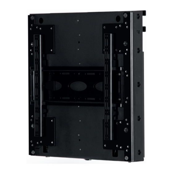
BT8601
UNIVERSAL
flat screen WALL MOUNT
with TOOL-LESS height ADJUSTMENT
INSTALLATION GUIDE
SPECIFICATIONS
• Recommended for screens up to 65"
• Max load:
BT8601-01 19kg - 36kg (42lbs - 79lbs)
BT8601-02 37kg - 62kg (81lbs -136lbs)
BT8601-03 63kg - 80kg (139lbs -176lbs)
• Suitable for displays with VESA
fixings up to 600 x 400mm
• Tool-less height adjustment of screen
• Height adjustment range: 400mm
• Mounts screen 124mm from wall
• Simple hook-on installation, all mounting
hardware included
®
& non-VESA
www.btechavmounts.com
BT8601-01
BT8601-02
62kg
BT8601-03
80kg
Advertisement

Subscribe to Our Youtube Channel
Related Manuals for B-Tech BT8601


Summary of Contents for B-Tech BT8601
- Page 1 TOOL-LESS height ADJUSTMENT INSTALLATION GUIDE SPECIFICATIONS • Recommended for screens up to 65" • Max load: BT8601-01 19kg - 36kg (42lbs - 79lbs) BT8601-02 37kg - 62kg (81lbs -136lbs) BT8601-03 63kg - 80kg (139lbs -176lbs) • Suitable for displays with VESA ®...
-
Page 2: Table Of Contents
Please check carefully to make sure there are no missing or defective parts - defective parts must never be used. B-Tech AV Mounts, its distributors and dealers are not liable or responsible for damage or injury caused by improper installation, improper use or failure to observe these safety instructions. In such cases, all guarantees will expire. - Page 3 A B-Tech AV Mounts recomenda que a instalação deste produto seja efectuada por um instalador de AV instalador de AV profissional ou outra pessoa devidamente habilitada. A B-Tech AV Mounts e os seus distribuidores e concessionários não são responsáveis por danos ou lesões causados por uma instalação incorrecta.
-
Page 4: Parts List
BT8601 PARTS LIST PLEASE KEEP THIS FOR FUTURE REFERENCE... - Page 5 PART NAME WALL PLATE BALANCE BOX ADAPTOR PLATE MOUNTING PLATE INTERFACE ARM VESA 600 ADAPTOR M8 x 12mm CSK SCREW M8 x 16mm CSK SCREW M8 x 8mm SCREW WASHER HEX KEY FIXING KIT M4 x 12mm SCREW M4 x 25mm SCREW M4 x 40mm SCREW M6 x 16mm SCREW M6 x 25mm SCREW...
-
Page 6: Installation Instructions
INSTALLATION INSTRUCTIONS MOUNT WALL BRACKET i. Measure the mounting height from the floor*. ii. Mark and then drill holes to mount item 1. iii. Mount item 1 level to the wall. *Note: Use the mounting height calcuator on: www.balancebox.eu to determine the height of wall bracket. WALL 300mm 406mm... - Page 7 MOUNT BALANCEBOX® TO WALL BRACKET Hook item 2 onto item 1. Note: Ensure the locking screws at the top of item 2 are unlocked. LOCKING SCREW...
- Page 8 SECURE AND LEVEL BALANCEBOX® i. Tighten locking screws at the top of item 2. ii Vertically level the BalanceBox by using the levelling screws at the bottom it item 2. i. LOCKING SCREWS ii. LEVELLING SCREWS...
- Page 9 ATTACH ADAPTOR PLATES TO THE BALANCEBOX® Fix item 3 to item 2 using item 8.
- Page 10 ATTACH MOUNTING PLATE Attach item 4 to item 3 using items 9 & 10. HEIGHT OPTIONS There are 3 height options. Use the fixing holes on item 3 as shown below. Option 1 Option 2 Option 3...
- Page 11 FIX INTERFACE ARMS TO REAR OF SCREEN Fix items 5 to the back of the screen using the interface kit (items A-M). Note: Ensure items 5 are positioned the correct way round. Note: Use spacers for screens with recessed fixngs SCREEN Using 600mm Adaptor Arms Portrait mounting assembly shown...
- Page 12 HOOK SCREEN ONTO MOUNTING PLATE Hook screen onto item 4. SCREEN WALL SCREEN ADJUSTMENT (OPTIONAL) To level the screen, use the height adjustment screws at the top of item 5. WALL SCREEN SCREEN HEIGHT ADJUSTMENT SCREW...
- Page 13 LOCK SCREEN ONTO MOUNTING PLATE Lock screen onto item 4 using the locking screws at the bottom of item 5. SCREEN WALL LOCKING SCREW SCREEN BALANCE SCREEN TO ENABLE HEIGHT ADJUSTMENT To counterbalance the screen use a drill driver with a 10mm socket at a low torque setting. i.
-
Page 14: Product Dimensions
BT8601 PRODUCT DIMENSIONS PLEASE KEEP THIS FOR FUTURE REFERENCE FRONT VIEW 8.2mm 600mm 39mm 5.5mm 8.5mm HEIGHT OPTIONS Maximum Height Minimum Height... - Page 15 PLEASE KEEP THIS FOR FUTURE REFERENCE BACK VIEW SIDE VIEW 483mm 465mm 121.9mm 406mm 30mm 300mm TOP VIEW 572mm 556mm 620mm THESE INSTRUCTIONS ARE INTENDED AS A GUIDE ONLY AND B-TECH ACCEPTS NO LIABILITY FOR THE ACCURACY OF THE INFORMATION CONTAINED IN THIS DOCUMENT.
-
Page 16: B-Tech Contact Details
©2019 B-Tech International Design & Manufacturing Ltd. All rights reserved. B-Tech AV Mounts is a division of B-Tech International Design & Manufacturing Ltd. B-Tech AV Mounts and the B-Tech logo are registered trade marks. All other brands and product names are trademarks of their respective owners.
Need help?
Do you have a question about the BT8601 and is the answer not in the manual?
Questions and answers