Table of Contents
Advertisement
Quick Links
OnSite™ Model 2701A/I
E1/T1 Ethernet Bridge (NTU)
User Manual
Important
This is a Class A device and is intended for use in a light industrial environment. It is not intended
nor approved for use in an industrial or residential environment.
Sales Office:
+1 (301) 975-1000
Technical Support:
+1 (301) 975-1007
E-mail:
support@patton.com
WWW:
www.patton.com
Part Number: 07MOS2701A/I-UM, Rev. A
Revised: February 26, 2017
Advertisement
Table of Contents

Subscribe to Our Youtube Channel
Related Manuals for Patton OnSite 2701A/I


Summary of Contents for Patton OnSite 2701A/I
- Page 1 This is a Class A device and is intended for use in a light industrial environment. It is not intended nor approved for use in an industrial or residential environment. Sales Office: +1 (301) 975-1000 Technical Support: +1 (301) 975-1007 E-mail: support@patton.com WWW: www.patton.com Part Number: 07MOS2701A/I-UM, Rev. A Revised: February 26, 2017...
- Page 2 E-mail: support@patton.com Trademark Statement The term OnSite is a trademark of Patton Electronics Company. All other trademarks presented in this document are the property of their respective owners. Copyright © 2017, Patton Electronics Company. All rights reserved. The information in this document is subject to change without notice. Patton Electronics assumes no liability for errors that may appear in this document.
- Page 3 3 Operation................................32 Contacting Patton for assistance.
- Page 4 .........................34 Contacting Patton for assistance Introduction ................................35...
-
Page 5: Table Of Contents
CopperLink Line Power 1101E PoE Extender User Manual Warranty Service and Returned Merchandise Authorizations (RMAs) ..............35 Warranty Coverage ............................35 Out-of-Warranty Service ..........................35 Returns for Credit ............................35 RMA Numbers ...............................36 Shipping Instructions ............................36 ...........................37 Compliance Information Regulatory Information ............................38... - Page 6 List of Figures Typical application ..............12 Data path .
- Page 7 List of Tables RJ-45 wire modes ............... 28 Terminal block wire modes .
- Page 8 83 describes how to use the command line interface (CLI) • For best results, read the contents of this guide before you install the OnSite 2701A/I. Precautions Notes and cautions, which have the following meanings, are used throughout this guide to help you become aware of potential Device modem problems.
- Page 9 OnSite 2701A/I E1/T1 Ethernet Bridge (NTU) User Manual About This Guide The alert symbol and IMPORTANT heading calls attention to important information. IMPORTANT...
- Page 10 OnSite 2701A/I E1/T1 Ethernet Bridge (NTU) User Manual About This Guide The alert symbol and CAUTION heading indicate a potential hazard. Strictly follow the instructions to avoid property damage. CAUTION The shock hazard symbol and CAUTION heading indicate a potential electric shock hazard. Strictly follow the instructions to avoid property damage caused by electric shock.
- Page 11 OnSite 2701A/I E1/T1 Ethernet Bridge (NTU) User Manual About This Guide In accordance with the requirements of council directive 2002/ 96/EC on Waste of Electrical and Electronic Equipment (WEEE), ensure that at end-of-life you separate this product from other waste and scrap and deliver to the WEEE collection system in your country for recycling.
- Page 12 Chapter 1 General information Chapter contents OnSite NTU overview ............................13 General attributes ............................13 Ethernet ................................13 Protocol support .............................13 PPP Support ..............................14 WAN Interfaces ..............................14 Management ..............................14 Front Panel Status LEDs and Console Port .....................14 Console port .............................15 Rear panel connectors and switches .........................15 Power connector ............................16...
-
Page 13: Onsite Ntu Overview
OnSite 2701A/I E1/T1 Ethernet Bridge (NTU) User Manual 1 • General information OnSite NTU overview The OnSite NTU enables the termination of E1 or T1 to 10/100Base-TX. The device is configured for plug- and-play operation. The device comes with an auto-sensing full-duplex 10/100Base-T Ethernet port, MDI-X cross-over switch, console port, and internal or external power supply. -
Page 14: Ppp Support
OnSite 2701A/I E1/T1 Ethernet Bridge (NTU) User Manual 1 • General information • Built-in ping and traceroute facilities. • Integrated DHCP server (RFC 2131). • DNS relay with primary and secondary name server selection. • Frame Relay with Annex A/D LMI, RFC 1490 and FRF.12 Fragmentation. -
Page 15: Console Port
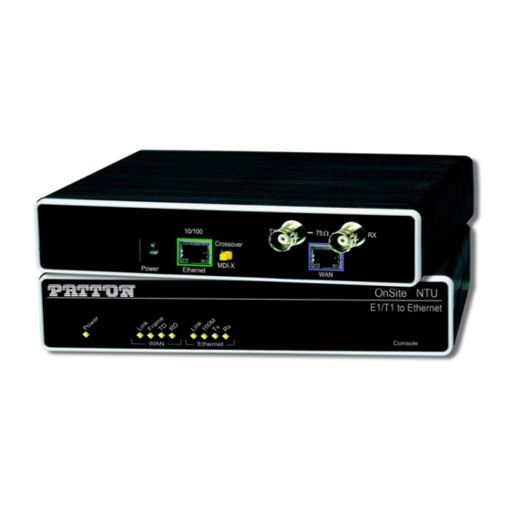
OnSite 2701A/I E1/T1 Ethernet Bridge (NTU) User Manual 1 • General information The status LEDs from left to right are (see table 2 for LED descriptions): • Power • E1/T1 TD, RD, CTS, and DTR • Ethernet Link, 100M, Tx, and Rx Table 2. -
Page 16: Power Connector
OnSite 2701A/I E1/T1 Ethernet Bridge (NTU) User Manual 1 • General information • Ethernet connector • MDI-X switch • WAN port (T1/E1) Power connector AC universal power supply. The OnSite device offers internal or external AC power supply options. •... -
Page 17: Applications Overview
OnSite 2701A/I E1/T1 Ethernet Bridge (NTU) User Manual 1 • General information Applications Overview OnSite NTUs offer a simple and reliable way for terminating E1/T1 to Ethernet. Figure 2. T1/E1 Application Applications Overview... - Page 18 Chapter 2 Installation Chapter contents Hardware Installation ............................19 What you will need ............................19 Interface cable installation ..........................19 Installing the AC power cord ..........................20 Logging onto the OnSite device ........................22 IP address modification ...........................23 Installing the Ethernet cables ..........................23 Web Operation and Configuration .........................24 Web Browser .............................24...
-
Page 19: Hardware Installation
OnSite 2701A/I E1/T1 Ethernet Bridge (NTU) User Manual 2 • Installation Hardware Installation If you are already familiar with OnSite device installation and configuration, this chapter will enable you to fin- ish the job quickly. Installation consists of the following: Preparing for the installation (see section “What you will... -
Page 20: Installing The Ac Power Cord
OnSite 2701A/I E1/T1 Ethernet Bridge (NTU) User Manual 2 • Installation RX connector TX connector (BNC) (BNC) Ethernet connector WAN connector (RJ-45) (RJ-48C) / 1 0 I - X Figure 3. Rear View of the NTU showing location of Ethernet and WAN connectors... - Page 21 OnSite 2701A/I E1/T1 Ethernet Bridge (NTU) User Manual 2 • Installation Do not connect the other end of the power cord to the power outlet at this Note time. 1. If your unit is equipped with an internal power supply, go to step 2. Otherwise, insert the barrel type con-...
-
Page 22: Logging Onto The Onsite Device
OnSite 2701A/I E1/T1 Ethernet Bridge (NTU) User Manual 2 • Installation 4. Connect the male end of the power cord to an appropriate power outlet. 5. Verify that the green Power LED is lit (see figure 6. Unplug the AC power cord from the OnSite device to power down the unit. -
Page 23: Ip Address Modification
OnSite 2701A/I E1/T1 Ethernet Bridge (NTU) User Manual 2 • Installation 2. On the PC, start a terminal emulation session (such as TeraTerm or HyperTerminal) at 9600 bps, 8 data bits, 1 stop bit, and no parity. 3. Connect the power cord to the power outlet. -
Page 24: Web Operation And Configuration
OnSite 2701A/I E1/T1 Ethernet Bridge (NTU) User Manual 2 • Installation 1. Connect a straight-through Ethernet cable between the PC’s NIC or PCMCIA Ethernet card and the Ethernet port on the rear panel of the OnSite device (see figure 3 on page 20). - Page 25 Chapter 3 Ethernet LAN Port Chapter contents Introduction ................................26 LAN Connections ..............................26 Ethernet Port.................................26...
- Page 26 OnSite 2701A/I E1/T1 Ethernet Bridge (NTU) User Manual 3 • Ethernet LAN Port Introduction The Ethernet LAN interface/port can be configured with two IP addresses, a primary and a secondary IP address. The configuration web page is found by following the path -> Services Configuration (in the Configu- ration Menu) ->...
- Page 27 OnSite 2701A/I E1/T1 Ethernet Bridge (NTU) User Manual 3 • Ethernet LAN Port Figure 9. Basic Ethernet port attributes For additional statistical parameters and a few configurable parameters, click on the hyperlink View advanced attributes... (See figure 10.) Figure 10. Advanced Ethernet port attributes The three configurable parameters are all either ‘true’...
- Page 28 OnSite 2701A/I E1/T1 Ethernet Bridge (NTU) User Manual 3 • Ethernet LAN Port Rarely do these parameters require a change from their default operation. Figure 11. Configurable Ethernet parameters Ethernet Port...
- Page 29 Chapter 4 Serial Port Configuration Chapter contents WAN Serial Port Configuration ..........................30 T1/E1 Interface Configuration ........................30 Configuring the OnSite 2701A for T1 Operation ..................30 Web Configuration ..........................30 Configuring the 2701A for E1 Operation ....................32 Web Configuration ..........................32...
- Page 30 OnSite 2701A/I E1/T1 Ethernet Bridge (NTU) User Manual 4 • Serial Port Configuration WAN Serial Port Configuration The OnSite NTU uses a T1/E1 interface for connection to standard WAN services. Below are the configura- tion options for the WAN interface.
- Page 31 OnSite 2701A/I E1/T1 Ethernet Bridge (NTU) User Manual 4 • Serial Port Configuration ration. (See figure 13.) Figure 13. T1 configuration Time Slot Select. For a T1 using all 24 time slots enter 1-24, for fractional T1 enter in any format for example: 1,2,3,5;...
- Page 32 OnSite 2701A/I E1/T1 Ethernet Bridge (NTU) User Manual 4 • Serial Port Configuration Configuring the 2701A for E1 Operation Launch Internet Explorer or similar web browser, type the IP address of the 2701A, enter Web Configuration. username superuser and password superuser. From the main page click on the T1/E1 > Configuration. (See figure 14.)
- Page 33 OnSite 2701A/I E1/T1 Ethernet Bridge (NTU) User Manual 4 • Serial Port Configuration This concludes the E1 interface configuration via the web browser, go to section “WAN Service Configuration” on page 50 for instructions on NTU/bridge and WAN service configuration.
- Page 34 Chapter 5 WAN Services Chapter contents WAN Services ...............................35 Configuring the OnSite NTU for E1 Operation ..................35 Web Configuration ..........................35 WAN Service Configuration..........................36 PPP Configuration ............................36 PPP Bridged ..............................36 PPP Bridged Remote Site Configuration ..................... 36 Central Site Configuration ........................
-
Page 35: Wan Services
OnSite 2701A/I E1/T1 Ethernet Bridge (NTU) User Manual 5 • WAN Services WAN Services Configuring the OnSite NTU for E1 Operation Launch Internet Explorer or similar web browser, type the IP address of the 2701A, enter Web Configuration. username and password . -
Page 36: Wan Service Configuration
OnSite 2701A/I E1/T1 Ethernet Bridge (NTU) User Manual 5 • WAN Services Once all options have been selected, click on the button at the bottom of the screen. Configure and Activate Additionally, save the configuration by going to the System Configuration > Save menu. -
Page 37: Central Site Configuration
OnSite 2701A/I E1/T1 Ethernet Bridge (NTU) User Manual 5 • WAN Services Figure 17. WAN services options 4. In the Description field, enter the description you wish. This is a mandatory field. Without a description, you cannot create the WAN service. -
Page 38: Lmi Management (Frame Relay Links)
OnSite 2701A/I E1/T1 Ethernet Bridge (NTU) User Manual 5 • WAN Services 2. On the Menu, go to Services Configuration, then to WAN. Delete the factory default WAN services already defined. 3. Click on Create a new service in the main window, select PPP bridged and click on the button. -
Page 39: Web Configuration Methods
OnSite 2701A/I E1/T1 Ethernet Bridge (NTU) User Manual 5 • WAN Services ITU User: The ITU Q.933 protocol will be used. The unit will operate as the User side of the connection. ITU Both: (NNI) The ITU Q.933 protocol will be used. The unit will operate as both the Network and User side of the connection. -
Page 40: Frame Relay Configuration
OnSite 2701A/I E1/T1 Ethernet Bridge (NTU) User Manual 5 • WAN Services All LMI configuration variables are contained under the “LMI Management” window found through the Ser- vices Configuration >LMI Management link. The following screen shows the configuration variables available. -
Page 41: Frame Relay Bridged
OnSite 2701A/I E1/T1 Ethernet Bridge (NTU) User Manual 5 • WAN Services Frame Relay bridged This application shows configuration for two OnSite devices in bridged mode. If using a third-party router at the Central site, review the router’s configuration for connection to a remote bridge. -
Page 42: Central Site Configuration
OnSite 2701A/I E1/T1 Ethernet Bridge (NTU) User Manual 5 • WAN Services TX Max PDU: 8192 Transmit side max PDU, default 8192(normally not changed from default) • • Channel segment size. The channel segment size is used to define fragmentation of the packets based on the Frame Relay Forum IA FRF.12. - Page 43 OnSite 2701A/I E1/T1 Ethernet Bridge (NTU) User Manual 5 • WAN Services 5. Click on Create a new service in the main window, select Frame relay bridged and click on the Configure button. 6. Click along the following path: Services Configuration > WAN > ‘Edit...’ Then click on Edit ‘Frame Relay Channel’.
- Page 44 Chapter 6 DHCP and DNS Configuration Chapter contents Introduction ................................45 DNS server option information ........................46 Default gateway option information .......................47 Additional option information ........................47 DNS server option information ........................48 Default gateway option information .......................49 Additional option information ........................49 DNS Relay ................................49 Configuring the DNS Relay ..........................49...
-
Page 45: Introduction
OnSite 2701A/I E1/T1 Ethernet Bridge (NTU) User Manual 6 • DHCP and DNS Configuration Introduction The 2701A offers a DHCP Server, DNS relay can hold two DNS server IP addresses in memory so the DNS relay can forward DNS queries and responses between the host user and the DNS server. -
Page 46: Dns Server Option Information
OnSite 2701A/I E1/T1 Ethernet Bridge (NTU) User Manual 6 • DHCP and DNS Configuration Figure 22. Example based on default range of IP address pool DNS server option information When a client requests an IP address from a DHCP server, the server can also send the IP addresses of the pri- mary and secondary DNS servers’... -
Page 47: Default Gateway Option Information
OnSite 2701A/I E1/T1 Ethernet Bridge (NTU) User Manual 6 • DHCP and DNS Configuration Default gateway option information The OnSite is the gateway all client traffic when Use local host as default gateway is checked (see figure 24). Additional option information You may wish to provide additional information to the clients on the DHCP subnet. -
Page 48: Dns Server Option Information
OnSite 2701A/I E1/T1 Ethernet Bridge (NTU) User Manual 6 • DHCP and DNS Configuration Figure 25. Example based on default range of IP address pool DNS server option information When a client requests an IP address from a DHCP server, the server can also send the IP addresses of the pri- mary and secondary DNS servers’... -
Page 49: Default Gateway Option Information
OnSite 2701A/I E1/T1 Ethernet Bridge (NTU) User Manual 6 • DHCP and DNS Configuration Default gateway option information The OnSite is the gateway all client traffic when Use local host as default gateway is checked (see figure 24). Additional option information You may wish to provide additional information to the clients on the DHCP subnet. - Page 50 OnSite 2701A/I E1/T1 Ethernet Bridge (NTU) User Manual 6 • DHCP and DNS Configuration Figure 28. Hyperlink path to the DNS Relay webpage Enter the IP address of the primary DNS server (see figure 29) and click on the Create button. Similarly enter the IP address of the secondary DNS server.
- Page 51 OnSite 2701A/I E1/T1 Ethernet Bridge (NTU) User Manual 6 • DHCP and DNS Configuration Figure 30. DNS Relay - configuration completed DNS Relay...
- Page 52 Chapter 7 System Configuration Chapter contents Introduction ................................53 Authentication...............................54 Alarm ..................................55 Remote Access ...............................56 Update ..................................56 Save ..................................57 Backup/Restore ..............................57 Restart ...................................58 Website Settings ..............................58 Error Log................................59 SNMP Daemon ..............................59 System Tools .................................60...
-
Page 53: Introduction
OnSite 2701A/I E1/T1 Ethernet Bridge (NTU) User Manual 7 • System Configuration Introduction The System Configuration item on the Configuration Menu opens to provide access to the following items: Authentication: allows you to control access to the OnSite device’s console and web configuration pages. -
Page 54: Authentication
OnSite 2701A/I E1/T1 Ethernet Bridge (NTU) User Manual 7 • System Configuration Authentication The OnSite manager controls access to the OnSite device’s console and web pages. The default defined user is superuser. See figure Figure 31. Authentication web page showing default superuser The superuser is the default administrative user and is given authority to configure the OnSite device, but the default settings have disabled the ability to authenticate through a remote connection. -
Page 55: Alarm
OnSite 2701A/I E1/T1 Ethernet Bridge (NTU) User Manual 7 • System Configuration Alarm Access the configuration and status of the alarms. Figure 33. Alarm Management web-page All OnSite devices have the ‘PP over Threshold’ and ‘NP over Threshold’ alarms. The Model 2701A has addi- tional alarms for the T1/E1 WAN port. -
Page 56: Remote Access
OnSite 2701A/I E1/T1 Ethernet Bridge (NTU) User Manual 7 • System Configuration Figure 34. Alarm & Alarm Error Log configuration The Alarm Error Log can be enabled or disabled. The severity level of the Alarm Log can also be configured. -
Page 57: Save
OnSite 2701A/I E1/T1 Ethernet Bridge (NTU) User Manual 7 • System Configuration Figure 36. Updating software Clicking on Options provides for selecting ‘Firmware Update Configuration.’ If enabled, the OnSite will pre- vent updating with incorrect software. Save To save configuration changes to non-volatile memory, it is essential to click on the Save button on this web- page. -
Page 58: Restart
OnSite 2701A/I E1/T1 Ethernet Bridge (NTU) User Manual 7 • System Configuration Figure 38. Saving or reloading previously saved configuration files Restart From this webpage, you can do a soft reboot of the OnSite or restore the OnSite to factory defaults. To restore to factory defaults, click on the box for Reset to factory default settings. -
Page 59: Error Log
OnSite 2701A/I E1/T1 Ethernet Bridge (NTU) User Manual 7 • System Configuration Error Log The Error Log webpage shows recent configuration errors and provides for the configuration of the Syslog. (See figure 41.) Two parameters are configurable for the Syslog. -
Page 60: System Tools
OnSite 2701A/I E1/T1 Ethernet Bridge (NTU) User Manual 7 • System Configuration Figure 42. SNMP Daemon configuration The Trap Table identifies the IP address of the SNMP trap along with its password. System Tools The System Tools webpage provides two utilities for testing network connectivity. The two utilities are ‘ping’... - Page 61 Chapter 8 SNTP Client Configuration Chapter contents Introduction ................................62 Configuring the SNTP Client ..........................62 SNTP Client Mode Configuration Parameters ....................62 SNTP Client General Configuration Parameters ....................63 System Clock Setting.............................63...
- Page 62 OnSite 2701A/I E1/T1 Ethernet Bridge (NTU) User Manual 8 • SNTP Client Configuration Introduction The Simple Network Time Protocol (SNTP) Client webpage contains the configurable parameters for either setting up the SNTP client or, in the absence of an SNTP server, setting the internal clock.
- Page 63 OnSite 2701A/I E1/T1 Ethernet Bridge (NTU) User Manual 8 • SNTP Client Configuration SNTP Client General Configuration Parameters The general configuration parameters for the SNTP client are for selecting your timezone and setting the poll- ing parameters for the client’s transmit packets.
- Page 64 OnSite 2701A/I E1/T1 Ethernet Bridge (NTU) User Manual 8 • SNTP Client Configuration If the OnSite device is rebooted, either soft or by power-cycling, the Clock Setting returns to its default value. System Clock Setting...
- Page 65 Chapter 9 3System Status Chapter contents System Status.................................66 Port Connection Status ...........................66 LAN Status ..............................67 WAN Status ..............................67 Hardware Status ..............................67 Defined Interfaces ............................67 Status LEDs................................68...
- Page 66 OnSite 2701A/I E1/T1 Ethernet Bridge (NTU) User Manual 9 • 3System Status System Status A quick but thorough summary of the OnSite device’s status is provided on this webpage, but it also has links to the detailed webpages for the key subsystems of the OnSite device.
- Page 67 OnSite 2701A/I E1/T1 Ethernet Bridge (NTU) User Manual 9 • 3System Status LAN Status There are two hyperlinks, LAN Settings... and DHCP Server Settings..., which go to the ‘LAN Connections’ and ‘DHCP Server’ webpages, respectively. The other parameters shown in LAN Status are as follows: •...
- Page 68 OnSite 2701A/I E1/T1 Ethernet Bridge (NTU) User Manual 9 • 3System Status Status LEDs The LEDs indicate the status of the Power, the WAN, Sync Serial port, and the Ethernet connection. All LED indicators will present the same looking profile (e.g., clear) when unlit due to being single color, water clear, high efficiency LEDs.
- Page 69 Contacting Patton for assistance Chapter contents Introduction ................................70 Contact information..............................70 Patton support headquarters in the USA ......................70 Alternate Patton support for Europe, Middle East, and Africa (EMEA) ............70 Warranty Service and Returned Merchandise Authorizations (RMAs)..............70 Warranty coverage ............................70 Out-of-warranty service ..........................71 Returns for credit ............................71...
-
Page 70: Warranty Service And Returned Merchandise Authorizations (Rmas)
RAS warranty and obtaining a return merchandise authorization (RMA). Contact information Patton Electronics offers a wide array of free technical services. If you have questions about any of our other products we recommend you begin your search for answers by using our technical knowledge base. Here, we have gathered together many of the more commonly asked questions and compiled them into a searchable database to help you quickly solve your problems. -
Page 71: Out-Of-Warranty Service
RMA#: xxxx 7622 Rickenbacker Dr. Gaithersburg, MD 20879-4773 USA Patton will ship the equipment back to you in the same manner you ship it to us. Patton will pay the return shipping costs. Warranty Service and Returned Merchandise Authorizations (RMAs) - Page 72 Appendix A Compliance Information Chapter contents Regulatory Information ............................73 ................................73 Safety ................................73 PSTN Regulatory ............................73 Radio and TV Interference (FCC Part 15) ......................73 CE Declaration of Conformity ..........................73 Authorized European Representative ........................73...
-
Page 73: A Compliance Information
OnSite 2701A/I E1/T1 Ethernet Bridge (NTU) User Manual A • Compliance Information Regulatory Information FCC Part 15, Class A • EN55022, Class A • • EN55024 Safety UL60950-1/CSA C22.2 No. 60950-1 • IEC/EN 60950-1 • AS/NZS 60950-1 • PSTN Regulatory •... -
Page 74: Specifications
Appendix B Specifications Chapter contents General Characteristics ............................75 Ethernet ................................75 T1/E1 Interface ..............................75 Protocol Support ..............................75 Support................................76 Management .................................76 Security .................................76 Dimensions ................................76 Power and Power Supply Specifications.........................76 AC universal power supply ........................76 48 VDC power supply ..........................76... -
Page 75: Line
OnSite 2701A/I E1/T1 Ethernet Bridge (NTU) User Manual B • Specifications General Characteristics • Compact low-cost NTU/bridge 10/100 Ethernet • Comprehensive hardware diagnostics, works with any operating system, easy maintenance and effortless • installation. Built-in web configuration. • Setup allows for standard IP address and unique method for entering an IP address and mask WITHOUT •... -
Page 76: Power Supply
OnSite 2701A/I E1/T1 Ethernet Bridge (NTU) User Manual B • Specifications PPP Support • Point-to-Point Protocol over HDLC PPPoE (RFC 2516) Client for autonomous network connection. Eliminates the requirement of installing • client software on a local PC and allows sharing of the connection across a LAN. - Page 77 OnSite 2701A/I E1/T1 Ethernet Bridge (NTU) User Manual B • Specifications Connect the equipment to a 36–60 VDC source that is electri- cally isolated from the AC source. The 36–60 VDC source is to be reliably connected to earth. CAUTION...
- Page 78 Appendix C Cable Recommendations Chapter contents Ethernet Cable ..............................79 Adapter..................................79...
- Page 79 OnSite 2701A/I E1/T1 Ethernet Bridge (NTU) User Manual C • Cable Recommendations Ethernet Cable Ethernet cable (P/N 10-2500) (refer to “RJ-45 shielded 10/100 Ethernet port” on page 81) The interconnecting cables shall be acceptable for external use and shall be rated for the proper application with respect to volt-...
- Page 80 Appendix D OnSite Physical Connectors Chapter contents RJ-45 shielded 10/100 Ethernet port........................81 RJ-45 non-shielded RS-232 console port (EIA-561)....................81 T1/E1 port (WAN) ...............................81 E1/T1 (RJ-48C Connector) ..........................81...
- Page 81 OnSite 2701A/I E1/T1 Ethernet Bridge (NTU) User Manual D • OnSite Physical Connectors RJ-45 shielded 10/100 Ethernet port Assuming the MDI-X switch is in the out position. Table 6. Ethernet Port (MDI-X switch in out position) Pin No. Signal Name...
- Page 82 OnSite 2701A/I E1/T1 Ethernet Bridge (NTU) User Manual D • OnSite Physical Connectors Table 8. T1/E1 Port Pin No. Signal Shield (Receive) Transmit (Ring) Transmit (Tip) Shield (Transmit) RX RX TX TX 1 2 3 4 5 6 7 8 Figure 48.
- Page 83 Appendix E Command Line Interface (CLI) Operation Chapter contents Introduction ................................84 CLI Terminology ..............................84 Local (VT-100 emulation) ..........................84 Remote (Telnet) ..............................84 Using the Console ............................84 Administering user accounts ..........................86 Adding new users ............................86 Setting user passwords .............................86 Changing user settings ............................87 Controlling login access ..........................87...
-
Page 84: Introduction
OnSite 2701A/I E1/T1 Ethernet Bridge (NTU) User Manual E • Command Line Interface (CLI) Operation Introduction The modem configuration and status can also be view and modified through the console, which is accessible through the RS-232 serial port or through a Telnet session over Ethernet. - Page 85 OnSite 2701A/I E1/T1 Ethernet Bridge (NTU) User Manual E • Command Line Interface (CLI) Operation → ethernet ?[After typing the “?” you will not see the “?”] delete show list clear → ethernet Then you may enter one of the keywords on the displayed list followed by a space and “?”...
-
Page 86: Administering User Accounts
OnSite 2701A/I E1/T1 Ethernet Bridge (NTU) User Manual E • Command Line Interface (CLI) Operation ip interface ip1 list secondaryipaddresses <enter> Secondary IP addresses for interface: ip1 IP Address -----|----------------- ----------------------- In this example there was not a secondary IP address. Now save the entire configuration in nonvolatile FLASH memory with the following command. -
Page 87: Changing User Settings
OnSite 2701A/I E1/T1 Ethernet Bridge (NTU) User Manual E • Command Line Interface (CLI) Operation Enter new password: *** Again to verify: *** → No check is made for any current password which may have been set for the Note user.
Need help?
Do you have a question about the OnSite 2701A/I and is the answer not in the manual?
Questions and answers