
Related Manuals for Axeon SOLO I


Summary of Contents for Axeon SOLO I
- Page 1 PAGE TITLE HERE (LONG) REVERSE OSMOSIS SYSTEM USER MANUAL MKT – 590 – A Page 1 of 22...
- Page 2 HEADER – SECTION 2 TITLE HERE This page is Intentionally left blank Page 2 of 22 MKT–590–B...
-
Page 3: Table Of Contents
OPERATING DO’S AND DON’TS ..........................6 SYSTEM SPECIFICATION CHART ..........................7 OPERATING LIMITS ..............................7 FEEDWATER AND OPERATING SPECIFICATIONS ..................... 8 SOLO I COMPONENT IDENTIFICATION AND DESCRIPTION ................... 9 PRE-FILTRATION ..............................10 POST-FILTRATION ..............................10 TUBING AND LOCKING CLIPS KIT ........................10 PERMEATE STORAGE ............................ -
Page 4: Introduction
INTRODUCTION The Solo I Reverse Osmosis System is a durable piece of equipment which, with proper care, will last for many years. This User Manual outlines installation, operation, maintenance and troubleshooting details vital to the sustained performance of your system. -
Page 5: Safety
SAFETY Defined below are the two safety headings used throughout this User Manual’s text. WARNING: INDICATES STATEMENTS THAT USED IDENTIFY DANGEROUS CONDITIONS OR PRACTICES. FAILURE TO FOLLOW WARNINGS COULD RESULT IN SERIOUS INJURY OR DEATH. CAUTION: INDICATES STATEMENTS THAT USED IDENTIFY CONDITIONS OR PRACTICES THAT COULD RESULT IN EQUIPMENT OR OTHER PROPERTY DAMAGE... -
Page 6: Operating Do's And Don'ts
OPERATING DO’S AND DON’TS • Change the cartridge filters regularly. • Monitor the system and keep a daily log. • Run the system as much as possible on a continuous basis. DON’T • Permit chlorine to enter or be present in the feed water. •... -
Page 7: System Specification Chart
SOLO I SYSTEM SPECIFICATION CHART Nothing has a greater effect on a reverse osmosis system than the feed water quality. If your feed water conditions change, please contact your local dealer or distributor to determine the proper recovery for your application. Before starting the RO system it is strongly suggested to obtain an up to date water analysis of the water to be treated. -
Page 8: Feedwater And Operating Specifications
FEEDWATER AND OPERATING SPECIFICATIONS MODELS SOLO I Flow Rates Permeate Flow Rate (gpd / lpd) 50 / 189 Feedwater TDS max (ppm) 1000 Product to Waste Ratio Connections Feed 1/4" QC Permeate 3/8” QC Concentrate 1/4" QC Membrane Membrane Quantity... -
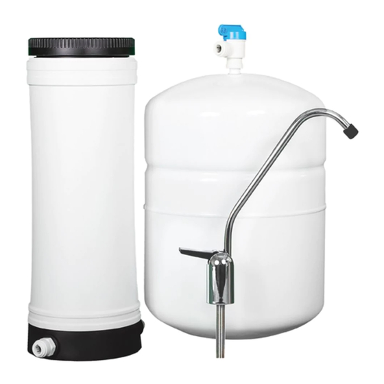
Page 9: Solo I Component Identification And Description
FEED WATER LINE (1/4” BLUE TUBING) 211477 5 MICRON SEDIMENT AND SINTERED CARBON BLOCK PRE FILTER 211479 SOLO I REVERSE OSMOSIS MEMBRANE ELEMENT (50 GPD) 211745 SOLO I REVERSE OSMOSIS SYSTEM LID 211481 3/8” QUICK CONNECT X 1/4" MNPT MALE CONNECTOR 200654 INLINE GRANULATED ACTIVATED CARBON POST FILTER (1/4”... -
Page 10: Pre-Filtration
Locking clips are only to be used on John Guest branded fittings. PERMEATE STORAGE Solo I systems are supplied with a bladder storage tank (item 1, pg. 9). Tank storage capacity is dependent on feed pressure and tank pressure. Typical usable capacity ranges from 2.4-3.2 gallons. -
Page 11: Membrane Information
MEMBRANE INFORMATION Solo I reverse osmosis systems come packaged with a proprietary Solo–Series Residential Membrane. General membrane element performance characteristics are listed on the following membrane specification chart. MEMBRANE ELEMENT SPECIFICATIONS Solo–Series Residential Membrane (Proprietary) Membrane Type: Polyamide Thin-Film Composite pH Range, Short Term Cleaning (30 Min.): 2-12... - Page 12 The claims made may not have been approved for use in all countries. The manufacturer assumes no obligation or liability for the information in this document. AXEON reserves the right to update this information periodically for the purposes of quality and accuracy. NO WARRANTIES ARE GIVEN; ALL IMPLIED WARRANTIES OF MERCHANTABILITY OR FITNESS FOR A PARTICULAR PURPOSE ARE EXPRESSLY EXCLUDED.
-
Page 13: System Installation
SYSTEM INSTALLATION When choosing a location to install the system, select an area with enough room for service to be performed on the system. Do not install system in direct sunlight or subject the system to temperature extremes and/or excess humidity. Use a tube cutter for cutting the supplied tubing. These can be found in your local hardware store. -
Page 14: Faucet Installation
SYSTEM INSTALLATION Connect the blue tubing to the inlet of the leak detector (item 4, pg. • 9). Connect a section of tubing from the leak detector outlet to the system (item 18, pg. 9) inlet. Install the provided red locking clips. •... -
Page 15: Permeate (Product Water) Connection
SYSTEM INSTALLATION • Tighten the nut. • Locate the faucet adaptor (item 12, pg. 9) and thread it on to the faucet shank hand tight. Once hand tight, tighten an additional 1/4 turn. PERMEATE (PRODUCT WATER) CONNECTION • Apply 3 – 4 wraps of Teflon tape to the threads of both 3/8” fittings (item 10, pg. 9) and install onto the inline filter. -
Page 16: Drain Saddle Installation
SYSTEM INSTALLATION FROM SYSTEM TO FAUCET • Apply 6 – 8 wraps of Teflon tape to the threaded stem on the top of the tank (item 1, pg. 9). Install tank valve (item 2, pg. 9) to the top of the tank.This only needs to be installed hand tight. - Page 17 SYSTEM INSTALLATION ANY RESTRICTIONS OR BLOCKAGE IN THE DRAIN LINE CAN CAUSE BACKPRESSURE, WHICH WILL INCREASE THE SYSTEM’S OPERATING PRESSURE. THIS CAN RESULT IN DAMAGE TO THE SYSTEM’S MEMBRANES AND COMPONENTS. Page 17 of 22 MKT–590–B...
-
Page 18: Membrane Installation And Handling
MEMBRANE INSTALLATION AND HANDLING MEMBRANE INSTALLATION / REPLACEMENT FEED WATER ADAPTOR VALVE MUST BE IN THE CLOSED POSITION BEFORE REPLACING THE MEMBRANE ELEMENT. Use the provided wrench to remove the black top cap (item 9, pg. 9) to the system. Remove the 2-stage filter (item 7, pg. -
Page 19: System Purging And Intial Start Up
SYSTEM PURGING AND INITIAL START UP CAREFULLY INSPECT YOUR SYSTEM BEFORE INITIAL START UP. CHECK THAT ALL THE PLUMBING CONNECTIONS ARE IN PLACE AND SECURELY FASTENED. ENSURE THAT THERE ARE NO KINKS OR TWISTS IN THE LINES. 1. Double check that all connections are made and the tubing is in securely. 2. -
Page 20: Troubleshooting
TROUBLESHOOTING TROUBLE SHOOTING CHART SYMPTOMS POSSIBLE CAUSES CORRECTIVE ACTION Feed valve is closed Open the feed valve. Inspect for leaks. If a leak is present, determine the location of the leak and repair as needed. Replace the textile in the leak Leak detector has engaged detector with a new one. -
Page 21: System Warranty
SYSTEM WARRANTY Warranty Terms Subject to the terms and conditions set forth hereinafter, the manufacturer (hereafter “Manufacturer”) warrants to the original purchaser (hereafter the “Customer”) that the systems and products manufactured by the Manufacturer are free from defects in material and in workmanship for twelve (12) months from the Warranty Commencement Date (as defined below) only when used strictly in accordance with the applicable operating instructions and within the range of the operating conditions specified by the Manufacturer for each such product. - Page 22 SYSTEM WARRANTY invoiced for the replacement part(s) provided. This Warranty does not cover or include labor and/or travel to the Customer’s premise or location or any other location. Charges of $1000 per day plus associated travel expenses will be incurred by the Customer in providing the Warranty Service at any location other than the Manufacturer’s main headquarters;...
Need help?
Do you have a question about the SOLO I and is the answer not in the manual?
Questions and answers