Table of Contents
Advertisement
Quick Links
705 Emmett Street Bristol, CT 06010
1-877-DynaLock www.dynalock.com
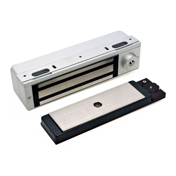
The electromagnetic lock and armature are ruggedly constructed and designed to provide years of trouble-free
service. Care must be taken during installation and use that the lock face and armature face are kept free of dirt,
rust, paint, or any other obstruction which may interfere with the lock and armature making good contact.
Familiarize yourself with the door and frame conditions. The lock must mount rigidly to the underside of the door
frame header and against the vertical strike jamb. The door mounted armature is supplied with hardware that allows
it to pivot slightly and pull away from the door as part of the delayed egress function.
NOTE: This lock does not change hands to match the hand of the door. Do not remove the coil assembly
from the lock housing.
NOTE: For locks ordered with the DSM option, please verify that two magnets are installed inside the
armature housing.
After mechanical installation is complete the 3101B needs to be wired and adjusted. A continuous power source, 12
or 24 VDC or VAC is required. Once low voltage power is supplied the unit is fully operational. Delay egress systems
also normally require fire panel tie-in. All other wiring is for selected options.
NOTE: Please see Egress Sensor Adjustment (page 8) before applying power.
3101B MANUAL
INSTALLATION INSTRUCTIONS
The 3101B Delay Egress System is a 1500 pound
holding force electromagnetic lock electronically
controlled to provide a 15 or 30 second delay in
unlocking.
The 3101B requires both mechanical and electrical
installation procedures as described herein.
When completed, a simple adjustment procedure to
set door movement will finalize the installation.
HANDLING
MECHANICAL INSTALLATION
ELECTRICAL INSTALLATION
Page 1
MODEL 3101B
DELAY EGRESS SYSTEM
INSTALLATION DESCRIPTION
02/08
Advertisement
Table of Contents

Related Manuals for DynaLock 3101B


Summary of Contents for DynaLock 3101B
-
Page 1: General Information
ELECTRICAL INSTALLATION After mechanical installation is complete the 3101B needs to be wired and adjusted. A continuous power source, 12 or 24 VDC or VAC is required. Once low voltage power is supplied the unit is fully operational. Delay egress systems also normally require fire panel tie-in. -
Page 2: Table Of Contents
MODEL 3101B DELAY EGRESS SYSTEM 705 Emmett Street Bristol, CT 06010 INSTALLATION INSTRUCTIONS 1-877-DynaLock www.dynalock.com MODEL #3101B BILL OF MATERIALS TABLE OF CONTENTS General Information........... 1 Bill Of Materials..........2 Using The Template........... 3 Mounting The Armature Assembly...... 4 Mounting The Lock..........5 Basic Set-Up............ -
Page 3: Using The Template
*FILLER PLATE MOUNTING REQUIRED REQUIRED REQUIRED *These items are available from DynaLock. USING THE TEMPLATE Fold the template on the dotted line to form a 90 degree 1/8" DIA. DRILL angle. Scoring the template with a straight edge and a PLACE AGAINST HEADER screwdriver will make it fold easier. -
Page 4: Mounting The Armature Assembly
MODEL 3101B DELAY EGRESS SYSTEM 705 Emmett Street Bristol, CT 06010 INSTALLATION INSTRUCTIONS 1-877-DynaLock www.dynalock.com MOUNTING THE ARMATURE ASSEMBLY Using the four #10 x 1” flat head sheet metal screws attach the armature mounting plate to the door. Firmly tighten the screws with a #2 phillips screw driver. -
Page 5: Mounting The Lock
MODEL 3101B DELAY EGRESS SYSTEM 705 Emmett Street Bristol, CT 06010 INSTALLATION INSTRUCTIONS 1-877-DynaLock www.dynalock.com MOUNTING THE LOCK Before installation begins remove the rear Electronics Cover, FIG. “A” End Cover and Sensor Cover Assembly (see page 14 for parts locations). Carefully unplug the sensor harness from the circuit... -
Page 6: Basic Set-Up
MODEL 3101B DELAY EGRESS SYSTEM 705 Emmett Street Bristol, CT 06010 INSTALLATION INSTRUCTIONS 1-877-DynaLock www.dynalock.com BASIC SET-UP Remove the Electronics Cover to expose the circuit board assembly. STANDARD SOFTWARE VERSION 2K1.1 (Factory Setting) - Voltage Selection Check that the voltage... -
Page 7: Basic Wiring
(N.C.) dry contacts from fire panel (check fire alarm control jumper “FA” - page 6). When the fire panel trips, the 3101B will release, the audible will sound a constant tone and the bi-color LED (LED1) will change to green. When the fire panel is reset, the 3101B will reset and lock. -
Page 8: Egress Sensor Adjustment
With the door closed and latched apply input power to terminals 1 & 2. Slide selector switch (DS1) #1 to the ON position to activate the Set-Up mode. EGRESS SENSOR Rotate the on-board keyswitch counter-clockwise. The 3101B should now ADJUSTMENT WHEEL be unlocked (LED1-OFF). -
Page 9: Indicator Descriptions
MODEL 3101B DELAY EGRESS SYSTEM 705 Emmett Street Bristol, CT 06010 INSTALLATION INSTRUCTIONS 1-877-DynaLock www.dynalock.com BUILT-IN KEYSWITCH OPERATION POSITION DESCRIPTION CENTER NORMAL / LOCKED CLOCKWISE (SPRING LOADED) RESET AFTER DELAY EGRESS ALARM COUNTER-CLOCKWISE BYPASS / UNLOCKED WITHOUT ALARM INDICATOR & AUDIBLE DESCRIPTIONS... -
Page 10: Optional Set-Up
MODEL 3101B DELAY EGRESS SYSTEM 705 Emmett Street Bristol, CT 06010 INSTALLATION INSTRUCTIONS 1-877-DynaLock www.dynalock.com OPTIONAL SET-UP - System Selector Switches Set the System Selector Switches (DS1) to address your specific system requirements. The normal factory setting is all switches off. -
Page 11: Option Wiring
9 & 10 will immediately release the across terminals 5 & 6 will reset and re-lock the lock without alarm. The door will remain unlocked for a 3101B following delayed egress and re-closure of period of time controlled by on-board adjustable timer door. - Page 12 MODEL 3101B DELAY EGRESS SYSTEM 705 Emmett Street Bristol, CT 06010 INSTALLATION INSTRUCTIONS 1-877-DynaLock www.dynalock.com OPTION WIRING MONITORING OUTPUT DESCRIPTIONS TYPICAL WIRING DELAY EGRESS OUTPUT NC C NO 13 14 15 Delay egress alarm monitoring. SPDT dry relay contacts rated 1Amp @ 24 Volts...
-
Page 13: Factory Wiring
3101B CIRCUIT BOARD NOTES: Harnesses J6 and J8 are only present if the 3101B is equipped with the DYN - Dynastat Force Sensor and/or DSM - Door Status Switch Options. Observe polarity when re-connecting the J5, J7 and J8 harness connectors. Orient these connectors with respect to harness wire colors as follows: Harness connectors J3 and J6 are not polarity sensitive. -
Page 14: Exploded Parts View
MODEL 3101B DELAY EGRESS SYSTEM 705 Emmett Street Bristol, CT 06010 INSTALLATION INSTRUCTIONS 1-877-DynaLock www.dynalock.com EXPLODED PARTS VIEW 1/4” 1-1/2” 1-1/2” 1/2” LEGEND ON NEXT PAGE Page 14 3101B MANUAL 02/08... - Page 15 MODEL 3101B DELAY EGRESS SYSTEM 705 Emmett Street Bristol, CT 06010 INSTALLATION INSTRUCTIONS 1-877-DynaLock www.dynalock.com EXPLODED PARTS VIEW LEGEND ITEM DESCRIPTION PART # Fas-Trak Baseplate 300011 #10x1” Self-Tapping Screw 10-24x1/2” Machine Screw Lock Housing Access Cover & Sensor Assembly 301037 8-32x3/8”...
- Page 16 PLEASE DELIVER THIS MANUAL AND THE KEYS TO THE END USER UPON COMPLETION OF THE 3101B INSTALLATION FOR PRODUCT SUPPORT AND PARTS ORDERING INFORMATION CONTACT: DynaLock Corp. 705 Emmett Street Bristol, CT 06010 Bus: (877) 396-2562 Toll-Free USA (860) 582-4761...
Need help?
Do you have a question about the 3101B and is the answer not in the manual?
Questions and answers