Advertisement
Quick Links
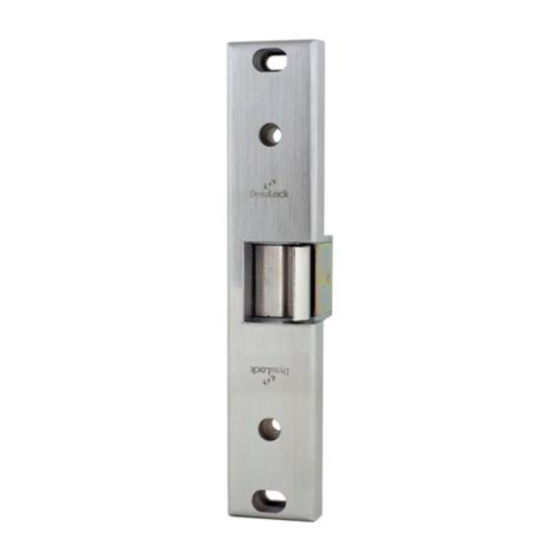
1661 SERIES COMMERCIAL ELECTRIC STRIKE
CENTERLINE LATCH ENTRY FOR RIM EXIT DEVICE
1. For new installations, surface mount 1661 strike first, then install exit device accordingly maintaining a
minimum of
⁄
" clearance.
3
1 6
2. Determine the horizontal center line 'G' of the Pullman Latch of the exit device, and transfer to frame stop.
(see fig. 1)
3. Determine the vertical center line of the Electric Strike 'X' by adding
and measure from the push side of the door to frame stop for 'X'.
4. Prepare door jamb as per template drawing for full surface mounting. (see preparation "V")
5. Ensure that strike insert is placed in the center most position on the faceplate prior to installation.
This allows for maximum adjustability when installation is complete (see Fig. 2).
6. Connect wires from power source to terminal screws on strike (polarity is not observed).
7. Using slotted holes in chassis, install exit device electric strike with 2 SHCS
screws provided.
8. Adjust chassis and electric insert (if necessary), horizontally, until Pullman Latch engages when door is
closed. Finally tighten screws.
Important: Be sure exit device dead locks when door is closed before proceeding to step 9.
9. Mark, drill and tap for the locking screws provided, and install to secure final location with
2 SHCS
1
⁄
- 20 x 1", screws provided.
4
Note:
If further adjustment is needed later, to correct door or weatherstrip misalignments, horizontally move
insert on its furrows by loosening screws under the face plate, and re-tighten when in the corrected
position (Fig. 2.).
Important:
The 1661 Electric Strike is never to be used as a door stop. Please install stops on frame in appropriate
locations. Ensure the exit device functions as intended for life safety concerns by verifying electric strike
and exit device compatibility. Maximum latch projection is essential to obtain full holding force.
705 EMMETT ST. P.O.BOX 2728 BRISTOL, CT 06011-2728 USA PHONE: 860-582-4761 FAX: 860-585-0338 EMAIL INFO@DYNALOCK.COM
Installation Instructions
©2005 DYNALOCK WWW.DYNALOCK.COM
⁄
" to dimension "R" (See Fig.1)
3
4
1
⁄
- 20 x 1", socket head cap
4
Advertisement

Related Manuals for DynaLock 1661 Series


Summary of Contents for DynaLock 1661 Series
- Page 1 Ensure the exit device functions as intended for life safety concerns by verifying electric strike and exit device compatibility. Maximum latch projection is essential to obtain full holding force. ©2005 DYNALOCK WWW.DYNALOCK.COM 705 EMMETT ST. P.O.BOX 2728 BRISTOL, CT 06011-2728 USA PHONE: 860-582-4761 FAX: 860-585-0338 EMAIL INFO@DYNALOCK.COM...
- Page 2 Fig.1 insert horizontally across the Note: DO NOT SCALE furrows. Original preparation is not disturbed. (Fig.2). SPECIFICATIONS SUBJECT TO CHANGE WITHOUT NOTICE. ©2005 DYNALOCK WWW.DYNALOCK.COM 705 EMMETT ST. P.O.BOX 2728 BRISTOL, CT 06011-2728 USA PHONE: 860-582-4761 FAX: 860-585-0338 EMAIL INFO@DYNALOCK.COM...
Need help?
Do you have a question about the 1661 Series and is the answer not in the manual?
Questions and answers