Advertisement
705 Emmett Street P.O. Box 9470 Forestville, CT 06011-9470 Phone (860)582-4761 Fax (860)585-0338
Familiarize yourself with the door and frame conditions prior to installation. The lock must rigidly mount to the
underside of the frame header. The armature is designed to pivot slightly to compensate for reasonable
misalignment.
Armature mounting hardware is supplied for a standard 1-3/4" thick door. For thicker doors order the following
special armature hardware kits:
Part #300687 for 2" thick doors.
Part #300688 for 2-1/4" thick doors.
HANDLING
The Electromagnetic lock and armature are
ruggedly constructed and designed to provide
years of trouble-free service. Care must be taken
during installation and use to keep the lock face
and armature face free from dirt, rust, burrs, paint,
or any other obstruction which may interfere with
the lock and armature making good contact.
The illustrations below depict typical installations of the Model #2511 Lock on single-outswing doors. The lock
assembly must be surface mounted to the underside of the frame header with the armature affixed to the inside
face of the door as shown.
LHRB DOOR
DynaLock Corp.
Electric Security Hardware
MOUNTING INSTRUCTIONS
SERIES 2511 ELECTROMAGNETIC LOCK
FOR A SINGLE OUTSWING DOOR
PLEASE READ BEFORE INSTALLATION
GENERAL MOUNTING INFORMATION
The lock assembly and door armature have been
plated for maximum corrosion resistance. To
ensure peak performance clean the lock and
armature faces with a mild detergent and a clean,
soft cloth, then apply a light coat of WD40 to protect
these surfaces. This need only be done when dirt
build-up is noticed.
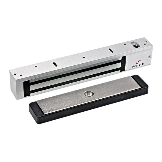
LOCK
ASSEMBLY
ARMATURE
page 1
MAINTENANCE
RHRB DOOR
.
Advertisement
Table of Contents

Related Manuals for DynaLock 2511 Series


Summary of Contents for DynaLock 2511 Series
- Page 1 DynaLock Corp. Electric Security Hardware 705 Emmett Street P.O. Box 9470 Forestville, CT 06011-9470 Phone (860)582-4761 Fax (860)585-0338 MOUNTING INSTRUCTIONS SERIES 2511 ELECTROMAGNETIC LOCK FOR A SINGLE OUTSWING DOOR PLEASE READ BEFORE INSTALLATION Familiarize yourself with the door and frame conditions prior to installation. The lock must rigidly mount to the underside of the frame header.
- Page 2 *FILLER PLATE REQUIRED *ANGLE BRACKET REQUIRED *These items are available from DynaLock PREPARE THE FRAME FOR MOUNTING THE LOCK ASSEMBLY Determine the hand of the door - LHRB or RHRB and look at the template edge for proper positioning of the template.
- Page 3 MOUNT THE ARMATURE TO THE DOOR Locate the two 3/16" dia.anti-spin pins from the hardware kit. Place the armature face-down on a soft surface ( i.e. the shipping carton ) and drive the anti-spin pins into the holes provided. Refer to Note #3 illustrations to select the correct mounting hardware and mount the armature.
- Page 4 2511 BILL OF MATERIAL TOOLS REQUIRED 1 - Electric Drill 1 - Mounting Instructions 1 - Template 1 - #2 Phillips Head Screw Driver 1 - Wiring Instructions 1 - Armature 1 - Soft-faced Mallet 1 - Electromagnetic Lock 1 - Armature Bolt assembly 1 - 3/16"...
- Page 5 ELECTROMAGNETIC LOCK 705 Emmett Street Bristol, CT 06010 WIRING INSTRUCTIONS 1-877-DynaLock www.dynalock.com OVERVIEW Familiarize yourself with the illustrations and instructions on this data sheet before attempting to wire this unit. The circuit board illustrations show a lock with every possible option - your lock may not have certain options.
- Page 6 SERIES 2500 & 2280 DynaLock ELECTROMAGNETIC LOCK 705 Emmett Street Bristol, CT 06010 WIRING INSTRUCTIONS 1-877-DynaLock www.dynalock.com POWER INPUT 12 / 24 VDC / VAC 12/24 VDC/VAC INPUT NORMALLY CLOSED STATION CONTROL(S), I.E. PUSHBUTTON, CURRENT DRAW: KEYSWITCH, ETC. 2280 0.68A @ 12VDC / 0.35A @ 24VDC...
- Page 7 ELECTROMAGNETIC LOCK 705 Emmett Street Bristol, CT 06010 WIRING INSTRUCTIONS 1-877-DynaLock www.dynalock.com LED OPTION The Bi-Color LED is used in conjunction with the Dynastat (DYN) option to display lock status in two colors - red or green and is pre-confi gured to operate on 24VDC. For 12VDC operation remove the outer resistor from the black wire. Connect the LED to the DYN as shown below.
- Page 8 TO THE END-USER UPON COMPLETION OF THE INSTALLATION FOR PRODUCT SUPPORT AND PARTS ORDERING INFORMATION CONTACT: DynaLock Corp. 705 Emmett Street Bristol, CT 06010 Bus: (877) DYNALOCK, Toll-Free USA (860) 582-4761 Fax: (860) 585-0338 DYNALOCK ON THE INTERNET: E-mail: info@dynalock.com Website: www.dynalock.com Page 4...
Need help?
Do you have a question about the 2511 Series and is the answer not in the manual?
Questions and answers