Advertisement
Table of Contents
- 1 General Information
- 2 Table of Contents
- 3 Bill of Materials
- 4 Using the Template
- 5 Mounting the Armature Assembly
- 6 Mounting the Lock
- 7 Basic Set-Up
- 8 Basic Wiring
- 9 Egress Sensor Adjustment
- 10 Indicator Descriptions
- 11 Optional Set-Up
- 12 Option Wiring
- 13 Factory Wiring
- 14 Exploded Parts View
- Download this manual
705 Emmett Street Bristol, CT 06010
1-877-DynaLock www.dynalock.com
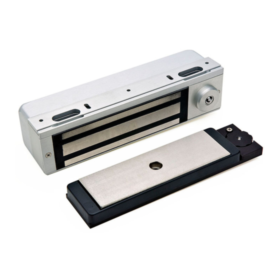
The electromagnetic lock and armature are ruggedly constructed and designed to provide years of trouble-free
service. Care must be taken during installation and use, so that the lock face and armature face are kept free of dirt,
rust, paint, or any other obstruction which may interfere with the lock and armature making good contact.
Familiarize yourself with the door and frame conditions. The lock must mount rigidly to the underside of the door
frame header and against the vertical strike jamb. The door mounted armature is supplied with hardware that allows
it to pivot slightly and pull away from the door as part of the delayed egress function.
NOTE: This lock does not change hands to match the hand of the door. Do not remove the coil assembly
from the lock housing.
NOTE: For locks ordered with the DSM option, please verify that two magnets are installed inside the
armature housing.
After mechanical installation is complete the 3101C needs to be wired and adjusted. A continuous power source, 12
or 24 VDC or VAC is required. Once low voltage power is supplied the unit is fully operational. Delay egress systems
also normally require fire panel tie-in. All other wiring is for selected options.
NOTE: Please see Egress Sensor Adjustment (page 8) before applying power.
3101C Gen II MANUAL
3101C
INSTALLATION INSTRUCTIONS
The 3101C Delay Egress System is a 1500 pound
holding force (holding force not evaluated by UL)
electromagnetic lock electronically controlled to
provide a 15 or 30 second delay in unlocking.
The 3101C requires both mechanical and electrical
installation procedures as described herein.
When completed, a simple adjustment procedure to
set door movement will finalize the installation.
HANDLING
MECHANICAL INSTALLATION
ELECTRICAL INSTALLATION
Page 1
EGRESS LOCK
(GENERATION II)
INSTALLATION DESCRIPTION
DELAYED
11/17
Advertisement
Table of Contents

Related Manuals for DynaLock 3101C


Summary of Contents for DynaLock 3101C
-
Page 1: General Information
ELECTRICAL INSTALLATION After mechanical installation is complete the 3101C needs to be wired and adjusted. A continuous power source, 12 or 24 VDC or VAC is required. Once low voltage power is supplied the unit is fully operational. Delay egress systems also normally require fire panel tie-in. -
Page 2: Table Of Contents
3101C EGRESS LOCK (GENERATION II) 705 Emmett Street Bristol, CT 06010 INSTALLATION INSTRUCTIONS 1-877-DynaLock www.dynalock.com MODEL #3101C BILL OF MATERIALS TABLE OF CONTENTS General Information........... 1 Bill Of Materials..........2 Using The Template........... 3 Mounting The Armature Assembly...... 4 Mounting The Lock..........5 Basic Set-Up............ -
Page 3: Using The Template
*SPACER PLATE MOUNTING REQUIRED REQUIRED REQUIRED *These items are available from DynaLock. USING THE TEMPLATE Fold the template on the dotted line to form a 90 degree 1/8" DIA. DRILL angle. Scoring the template with a straight edge and a PLACE AGAINST HEADER screwdriver will make it fold easier. -
Page 4: Mounting The Armature Assembly
Armature should have approximately 1/4” of free play, under slight spring tension. 8-32x3/8” ARMATURE ARMATURE MOUNTING ARMATURE HOUSING PLATE ASSEMBLY HOUSING SCREW ARMATURE SPRING 0.360”L ARMATURE SPACER 5/16-18x1” TURNED ARMATURE MOUNTING SCREW Page 4 3101C Gen II MANUAL 11/17... -
Page 5: Mounting The Lock
13 for connector information). If the lock wiring and set-up are not being done at this time replace the Electronics Cover and see that these instructions are left for the electrical installer. FAS-TRAK FIG. “C” TABS SCREW SCREW 1-1/8” OFFSET VERTICAL JAMB LOCK Page 5 3101C Gen II MANUAL 11/17... -
Page 6: Basic Set-Up
OFF position for basic lock operation. Switch 1 will be used during sensor adjustment (page 8). Switches 2 through 7 are only used for options described on page 10. (Factory Setting) Page 6 3101C Gen II MANUAL 11/17... -
Page 7: Basic Wiring
A power limited, UL Listed power supply for security applications is required for UL294 installations. When the 3101C is used with a fire alarm control panel, wiring must be done for fail-safe operation. Suitability of all wiring leads is to be determined based on end- user product requirements. -
Page 8: Egress Sensor Adjustment
With the door closed and latched apply input power to terminals 1 & 2. Slide selector switch (DS1) #1 to the ON position to activate the Set-Up mode. EGRESS SENSOR Rotate the on-board keyswitch counter-clockwise. The 3101C should now ADJUSTMENT WHEEL be unlocked (Multicolor LED Array OFF). -
Page 9: Indicator Descriptions
& requires reset. FAST BLINK RED POOR MAGNETIC Rapid pulse rate until problem BOND is corrected (only functional with Dynastat Force Sensor option). Page 9 3101C Gen II MANUAL 11/17... -
Page 10: Optional Set-Up
3 SEC. EGRESS DELAY 15 SEC. 30 SEC. MASTER AUDIBLE ENABLED DISABLED NORMALLY FIRE ALARM NORMALLY INPUT SETTING OPEN CLOSED EGRESS SENSOR ENABLED DISABLED UNUSED SPARE Only applies to terminals 9&10 (see next page) Page 10 3101C Gen II MANUAL 11/17... -
Page 11: Option Wiring
9 & 10 will immediately release the lock without across terminals 5 & 6 will reset and re-lock the alarm. The door will remain unlocked for a period of time 3101C following delayed egress and re-closure of controlled by on-board adjustable timer S2. To increase the door. - Page 12 POWER SUPPLY Contacts change state upon initiation of delayed egress, after the nuisance delay has elapsed. They remain in that state until door is closed and reset. SECURE NOTE: INDICATORS ARE NOT INCLUDED Page 12 3101C Gen II MANUAL 11/17...
-
Page 13: Factory Wiring
3101C CIRCUIT BOARD NOTES: Harnesses J6 and J8 are only present if the 3101C is equipped with the DYN - Dynastat Force Sensor and/or DSM - Door Status Switch Options. Observe polarity when re-connecting the J5, J7, J8 harness connectors. Orient these connectors with... -
Page 14: Exploded Parts View
DELAYED 3101C EGRESS LOCK (GENERATION II) 705 Emmett Street Bristol, CT 06010 INSTALLATION INSTRUCTIONS 1-877-DynaLock www.dynalock.com EXPLODED PARTS VIEW 1/4” 1-1/2” 1-31/32” 1/2” LEGEND ON NEXT PAGE Page 14 3101C Gen II MANUAL 11/17... - Page 15 8-32x3/8” Armature Mtg. Screw Disc Magnet (DSM only) 301289 Armature 300373 Compression Spring 0.360”L Armature Spacer 5/16-18x1” Armature Bolt (turned) * Part of Hardware Kit (301556) Refer to Page 14 for parts locations. Page 15 3101C Gen II MANUAL 11/17...
- Page 16 PLEASE DELIVER THIS MANUAL AND THE KEYS TO THE END USER UPON COMPLETION OF THE 3101C INSTALLATION FOR PRODUCT SUPPORT AND PARTS ORDERING INFORMATION CONTACT: DynaLock Corp. 705 Emmett Street Bristol, CT 06010 Bus: (877) 396-2562 Toll-Free USA (860) 582-4761...
Need help?
Do you have a question about the 3101C and is the answer not in the manual?
Questions and answers