Table of Contents
Advertisement
Quick Links
9327
LOGIC PROBE
Instruction Manual
Jan. 2019 Revised edition 11
9327A980-11 19-01H
Warranty
Warranty malfunctions occurring under conditions of normal use in
conformity with the Instruction Manual and Product Precautionary
Markings will be repaired free of charge. This warranty is valid for a pe-
riod of one (1) year from the date of purchase. Please contact the dis-
tributor from which you purchased the product for further information
on warranty provisions.
Introduction
Thank you for purchasing the HIOKI Model 9327 LOGIC PROBE.
To obtain maximum performance from the device, please read
this manual first, and keep it handy for future reference.
Overview
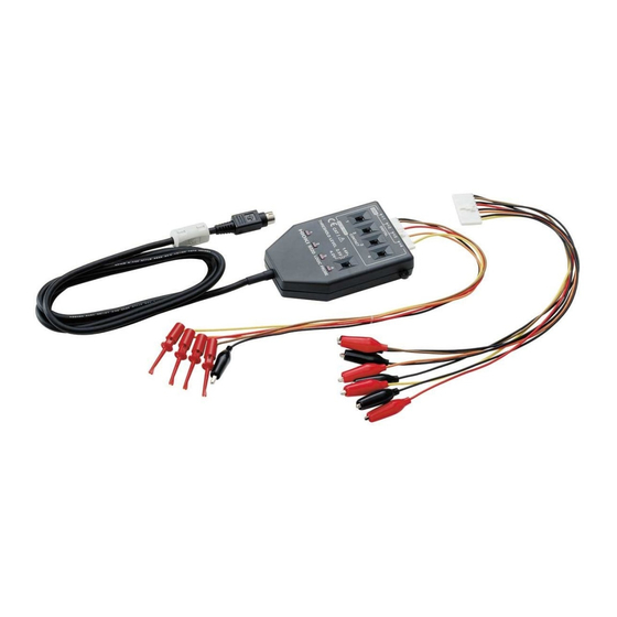
The 9327 is a logic probe with indicator. It is connected to the
logic input unit for the MR8875,MR8827,or MR8847 MEMORY
HiCORDER. It is equipped with a selector for each channel, so
that the input type can be switched between digital input and
contact input for each channel. This makes it possible to use
this probe for a variety of applications such as measurement of
electronic circuits and operation timing of mechanical relays.
Inspection and Maintenance
Initial Inspection
When you receive the device, inspect it carefully to ensure that
no damage occurred during shipping. If damage is evident, or if
it fails to operate according to the specifications, contact your
dealer or Hioki representative.
Confirming package contents
• 9327 LOGIC PROBE ................................1
• IC clip leads ..............................................1
• Alligator clip leads.....................................1
• Carrying case............................................1
• Instruction manual ....................................1
Preliminary Checks
• Before using the device the first time, verify that it operates
normally to ensure that the no damage occurred during stor-
age or shipping. If you find any damage, contact your dealer
or Hioki representative.
• Before using the device, make sure that the insulation on the
probes is undamaged and that no bare conductors are
improperly exposed. Using the device in such conditions
could cause an electric shock, so contact your dealer or Hioki
representative for repair.
Maintenance and Service
EN
• To clean the device, wipe it gently with a soft cloth moistened
with water or mild detergent. Never use solvents such as
benzene, alcohol, acetone, ether, ketones, thinners or gaso-
line, as they can deform and discolor the case.
• If the device seems to be malfunctioning, contact your dealer
or Hioki representative.
• Pack the device so that it will not sustain damage during ship-
ping, and include a description of existing damage. We cannot
accept responsibility for damage incurred during shipping.
Safety Information
This manual contains information and warnings essential for
safe operation of the device and for maintaining it in safe oper-
ating condition. Before using it, be sure to carefully read the fol-
lowing safety precautions.
This device is designed to comply with IEC 61010 Safety
Standards, and has been thoroughly tested for safety
prior to shipment. However, mishandling during use
could result in injury or death, as well as damage to the
device. Be certain that you understand the instructions
and precautions in the manual before use. We disclaim
any responsibility for accidents or injuries not resulting
directly from device defects.
Symbols Affixed to the Instrument
IIndicates cautions and hazards. Refer to the "Usage Notes"
section of the instruction manual for more information.
In this document, the risk seriousness and the hazard levels are
classified as follows.
Indicates an imminently hazardous situation that will result
in death or serious injury to the operator.
IIndicates a potentially hazardous situation that may result
in death or serious injury to the operator.
result in minor or moderate injury to the operator or dam-
age to the device or malfunction.
Indicates advisory items related to performance or cor-
rect operation of the device.
Measurement categories
To ensure safe operation of measurement devices, IEC 61010 estab-
lishes safety standards for various electrical environments, categorized
as CAT II to CAT IV, and called measurement categories.
CAT II: Primary electrical cir-
cuits in equipment connected to
an AC electrical outlet by a pow-
er cord (portable tools, house-
hold appliances, etc.)
CAT II
covers directly measuring elec-
trical outlet receptacles.
CAT III: Primary electrical circuits
of heavy equipment (fixed instal-
lations) connected directly to the
distribution panel, and feeders from the distribution panel to outlets.
CAT IV: The circuit from the service drop to the service entrance, and
to the power meter and primary overcurrent protection device (distribu-
tion panel).
Using a measurement device in an environment designated with a
higher-numbered category than that for which the device is rated could
result in a severe accident, and must be carefully avoided.
Use of a measurement instrument that is not CAT-rated in CAT II to
CAT IV measurement applications could result in a severe accident,
and must be carefully avoided.
Usage Notes
Follow these precautions to ensure safe operation and to obtain
the full benefits of the various functions.
• The main unit's GND and the logic input terminals GND
are not insulated. Handle these items carefully in order
to avoid electric shock or a short circuit accident.
• The maximum input voltage is 50 VDC. Attempting to
measure voltage in excess of the maximum input could
destroy the device and result in personal injury or death.
Do not allow the device to get wet, and do not take measure-
ments with wet hands. This may cause an electric shock.
• Do not store or use the device where it could be exposed to
direct sunlight, high temperature or humidity, or condensa-
tion. Under such conditions, the device may be damaged
and insulation may deteriorate so that it no longer meets
specifications.
• This device is not designed to be entirely water- or dust-proof.
Do not use it in an especially dusty environment, nor where it
might be splashed with liquid. This may cause damage.
• To avoid damage to the device, protect it from physical
shock when transporting and handling. Be especially careful
to avoid physical shock from dropping.
This device may cause interference if used in residential areas. Such
use must be avoided unless the user takes special measures to reduce
electromagnetic emissions to prevent interference to the reception of
radio and television broadcasts.
Specifications
Accuracy guaranteed for one year at 23°C±5°C (73°F±9°F), 35% RH
to 80% RH
The number of chan-
4 (having a common ground with the main unit
nels
and between channels.)
Input type
Digital input / Contact input
Input type can be selected for each channels.
Open collector outputs can be directly mea-
sured using contact inputs.
Input resistance
1 M±5% (Digital input: 0 V to +5 V)
500 k or more (Digital input: +5 V to +50 V)
Pull-up resistance
2 k(Contact inputs: supplied with a voltage
of +5 V via the input terminal)
Detecting level
Digital input
Contact input
Threshold
Detecting resistance value
value
more than 1.5 k
opened (Output L)
1.4 V range 1.4 V±0.3 V
less than 500
shorted (Output H)
more than 3.5 k
opened (Output L)
2.5 V range 2.5 V±0.4 V
less than 1.5 k
shorted (Output H)
more than 25 k
opened (Output L)
4.0 V range 4.0 V±0.5 V
less than 8 k
shorted (Output H)
Response pulse width 100 ns or more
Maximum input voltage 0 VDC to +50 VDC
Maximum rated current 100 mA
Operating temperature
0°C to 40°C (32°F to 104°F), 80% RH (no
and humidity ranges
condensation)
Storage temperature
-10°C to 50°C (14°F to 122°F), 90% RH (no
and humidity ranges
condensation)
Operating environment Altitude up to 2000 m (6562-ft.),
Pollution degree 2, indoors
Dimensions
Approx. 62W x 94H x 20D mm (2.44"W x
3.70"H x 0.79"D) (excluding protrusions)
Connector cable length Approx. 1500 mm (59")
Probe tip cable length Approx. 300 mm (11.8")
Mass
Approx. 150 g (5.3 oz.) (including connector
cable, excluding input leads)
Accessories
IC clip leads, Alligator clip leads, Carrying
case, Instruction manual
Applicable Standards
Safety
EN 61010
EMC
EN 61326 Class A
Product warranty
1 year
period
Parts Names
Alligator clip leads
For contact input
When replacing the leads, pull
out the leads while pressing the
connector knob downward.
Input selector
Switches the input type.
• Digital input (DIGITAL)
Connector knob
(Input for measuring digital
ICs.)
• Contact input (CONTACT)
(Input for measuring contacts.)
Threshold value selector
Switches the threshold
value.
IC clip leads
For digital input
Indicator
Indicates the input condition of each
channel.
8-pin connector
• Digital input
Lights when the level signal (H) is
For details on connection,
input.
refer to the instruction manual
• Contact input
of the each instrument.
Lights when alligator clips are
shorted.
Using Method
When measuring digital signals (Digital input)
Connect the IC clip leads to the device.
Alligator clip
1.
Set the input selector to DIGITAL.
2.
IC clips
Connect the alligator clip to the circuit
3.
ground.
4.
Use the threshold value selector to se-
lect the threshold value.
Connect the IC clips to the measure-
5.
IC clip leads
ment object.
When measuring the contact signal (Contact input)
Alligator clips
Connect the Alligator clip leads to the
1.
device.
2.
Set the input selector to CONTACT.
Connect the alligator clip to the mea-
3.
surement object.
Alligator clip leads
Advertisement
Table of Contents


Need help?
Do you have a question about the 9327 and is the answer not in the manual?
Questions and answers