Table of Contents
Advertisement
Quick Links
Advertisement
Chapters
Table of Contents

Related Manuals for Hioki 9274


Summary of Contents for Hioki 9274
-
Page 3: Table Of Contents
────────────────────────────────────── 目 次 はじめに 安全について 点 検 ご使用にあたっての注意 1.概 要 1.1 製品概要 1.2 特 長 2.各部の名称 3.操作方法 3.1 使用上の注意 3.2 操作方法 4.製品仕様 ──────────────────────────────────────... -
Page 4: はじめに
────────────────────────────────────── はじめに このたびは、日置 9274クランプオンAC/DCセンサ" をご選定い ただき誠にありがとうございました。この製品を十分に活用いただき、末 長くご使用いただくためにも、取扱説明書はていねいに扱い、いつも手元 に置いてご使用ください。 安全について 安全記号 この取扱説明書には、本器を安全に操作し、安全な状態を保つのに要する 情報や注意事項が記載されています。本器を使用する前に、下記の安全に 関する事項をよくお読みください。 ・操作者は、機器上の表示されている マークのとこ ろについて、取扱説明書の マーク該当箇所を参照 し、機器の操作をしてください。 ・操作者は、取扱説明書の中の マークのところは必 ず説明を読む必要があることを示します。 ○本説明書の注意事項には重要度に応じて以下の表記がされています。 操作や取扱を誤ると、使用者が死亡または重傷につなが 危険 る危険性が極めて高いことを意味します。 操作や取扱を誤ると、使用者が傷害を負う場合、または 注意 機器を損傷する可能性があることを意味します。 製品性能および操作上でのアドバイス的なことを意味し 注記 ます。 ──────────────────────────────────────... -
Page 5: 点 検
────────────────────────────────────── 点 検 本器が届きましたら、輸送中において異常または破損がないかを点検して ください。万一、破損あるいは仕様どおり動作しない場合は、最寄りの代 理店か営業所にご連絡ください。 ──────────────────────────────────────... -
Page 6: ご使用にあたっての注意
────────────────────────────────────── ご使用にあたっての注意 本器を安全にご使用いただくために、また機能を十二分に活用いただくた めに、下記の注意事項をお守りくださるようお願いいたします。 ・運搬および取扱の際は振動、衝撃を避けてください。特に、落 下などによる衝撃に注意してください。 ・直射日光や高温、多湿、結露させるような環境下での保存、使 用は避けてください。変形、絶縁劣化を起こし、仕様を満足し なくなります。 ・使用前には、過酷な保存や輸送などによる故障がないかを、点 検と動作確認をしてから使用してください。故障を確認した場 合は、最寄りの代理店か営業所にご連絡ください。 ・コア部つき合わせ面にゴミなどが付着した場合は、測定に影響 がでますので柔らかい布にて軽く拭き取ってください。 ・コア部に機械的な衝撃を加えないようにしてください。コア面 注意 に傷がついた場合は正確な測定ができません。 ・センサケーブル(特にセンサ側の付け根)は、断線による故障 を防ぐため折ったり引っ張たりせず取扱には注意してくださ い。 ・カレントモニタおよびセンサの損傷を防ぐため、電源が入った 状態ではセンサコネクタの抜き差しを行わないでください。 ・カレントモニタの電源を投入した状態では、被測定導体を挟み 込むとき以外はセンサの先端を閉じておいてください。(開い たままにすると損傷してしまう恐れがあります) ・センサを分解すると開閉機構などを損傷し、使用できなくなり ます。 ──────────────────────────────────────... -
Page 7: 1.概 要
────────────────────────────────────── 1. 概 要 1.1 製品概要 本器は、3270カレントモニタに接続することにより、被測定導体を切 断することなく被測定導体を挟み込むだけで電流波形を出力することがで きます。 記録計、オシロスコープなどで簡単に電流波形を記録、観測することがで きます。 1.2 特 長 ・高確度な電流検出 ・簡易な電流測定 ・センサの完全な互換性 ・広帯域な周波数特性 DC〜10MHz(−3dB) ・小型で低電流測定可能 ・過大入力時の保護機能 ・独自開発の薄膜ホール素子採用 ────────────────────────────────────── 1.2 特 長... -
Page 8: 2.各部の名称
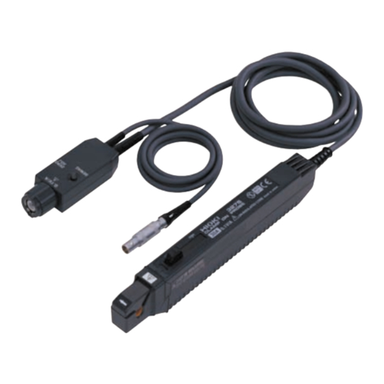
────────────────────────────────────── 2. 各部の名称 電流方向マーク UNLOCK 表示 レバー つき合わせ面 センサケーブル コア部 センサコネクタ ──────────────────────────────────────... -
Page 9: 3.操作方法
────────────────────────────────────── 3. 操作方法 3270カレントモニタの取扱説明書の『測定方法』を合わせて参照して ください。 3.1 使用上の注意 ・クランプ製品は、短絡、人身事故などを避けるために、600Vピ 危険 ーク以下の電路で使用してください。 ・クランプコアの先端を開いたときの短絡、人身事故などを避け るために、裸導体には使用しないでください。コアおよびシー ルドケースが絶縁されていません。 3.2 操作方法 (1) レバーを引き、センサ部先端を開いてください。 (2) センサ部に表示してある電流方向マークの矢印が負荷側を向くようにし て、被測定導体が中央になるようにクランプしてください。 注記 中央にしないと導体位置の影響を受ける場合があります (3) レバーを UNLOCK の表示が消えるまで押し、レバーが確実にロッ クされたことを確認してください。 注記 UNLOCK が表示された状態では、正確な測定ができません ────────────────────────────────────── 3.2 操作方法... - Page 10 ────────────────────────────────────── ・最大入力範囲を超える電流を入力しないでください。最大入力 範囲は測定電流の周波数によって異なります。(図2参照) ・最大入力範囲を超える電流を入力した場合は、センサ部の発熱 により内部回路の保護機能が働くため正常な出力をしなくなり ます。ただちに入力が無い状態(被測定導体からセンサを外す か入力電流をゼロにする)にしてください。(再び正常な動作 をするまでには十分な冷却時間が必要となります) ・上記のことを繰り返し行ったり最大入力範囲を超える電流を入 力し続けたりすると本器を損傷する恐れがあります。 注意 ・センサ部先端を開くときは、必ずレバーにて操作してくださ い。ロック状態で上コアを押すと、開閉機構が損傷を受けま す。 注記 ・電源投入直後は、カレントモニタおよび本器の自己発熱の影響などにより オフセットドリフトが大きい場合があります。 ・オフセット電圧は、周囲温度などによりドリフトしますので、連続測定を 行う際には注意が必要です。 ・測定電流値の大きさおよび周波数によっては、共振により音が発生する場 合がありますが、測定には影響ありません。 ・近接して大電流電路がある場合などは、外部磁界の影響を受ける場合があ ります。 ────────────────────────────────────── 3.2 操作方法...
-
Page 11: 4.製品仕様
────────────────────────────────────── 4. 製品仕様 確度は23℃± 3℃、電源投入後30分にて 定 格 電 流:20A(AC+DC成分) 出 力 電 圧:2V/20A(AC+DC成分) 出 力 抵 抗:50Ω 入 力 イ ン ピ ー ダ ン ス:55Hzにて0.1mΩ以下 (図1参照) 連 続 最 大 入 力 範 囲:20A (図2参照) 最 大 ピ ー ク 電 流 値:非連続で50A(ピーク値) 振... - Page 12 ────────────────────────────────────── 図1.入力インピーダンス 図2.最大入力範囲 図3.周波数帯域 (特性例) ──────────────────────────────────────...
- Page 15 Contents Introduction Notes on Safety Inspection Notes on Use Chapter 1 General 1.1 Product Overview 1.2 Features Chapter 2 Identification of Indicators Chapter 3 Measurement Procedure 3.1 Notes on Use 3.2 Measurement Procedure Chapter 4 Product Specifications...
-
Page 17: Introduction
Introduction Thank you for purchasing this Hioki 9274 Clamp-On AC/DC Sensor. In order to use this product effectively and to ensure that it enjoys a long operational life, read this Instruction Manual carefully and then retain it for future reference. -
Page 18: Inspection
When the unit is delivered, check and make sure that it has not been damaged in transit. In particular, check the accessories, core section, and sensor connector. If the unit is damaged, or fails to operate according to the specifications, contact your dealer or Hioki representative. -
Page 19: Notes On Use
If damage is found, contact your dealer or Hioki representative. • If there is any type of dust or dirt on the core contact surfaces, measurements may be affected. - Page 20 • When the power for the Current Monitor is on, keep the CAUTION core section closed, except when clamping them onto the conductor to be measured. (The facing surface of the core section can be scratched while it is open.) •...
-
Page 21: Chapter 1 General
Chapter 1 General 1.1 Product Overview When connected to the 3270 Current Monitor, this clamp- on sensor can output current waveforms without any need to cut the conductor being measured, simply by clamping the sensor onto the conductor. This equipment can thus be used in conjunction with a recorder, an oscilloscope, or other such equipment in order to record and measure current waveforms. - Page 22 Chapter 1 General...
-
Page 23: Chapter 2 Identification Of Indicators
Chapter 2 Identification of Indicators Current direction mark "UNLOCK" indication "OPEN" indication Lever Facing surface Sensor cable Core section Sensor connector Chapter 2 Identification of Indicators... - Page 24 Chapter 2 Identification of Indicators...
-
Page 25: Chapter 3 Measurement Procedure
Chapter 3 Measurement Procedure For details on how to take measurements, refer to Section 1.4, "Measurement Procedure" of the 3270 Current Monitor Instruction manual. 3.1 Notes on Use In order to prevent short circuits and injury or DANGER death, only use this sensor on circuits carrying less than 600 V peak. - Page 26 If the conductor being measured is not centered, the NOTE results may be affected by its position. (3) Press the lever forward until the "UNLOCK" indication disappears, and confirm that the lever is completely locked. Accurate measurement is not possible if "UNLOCK" is NOTE visible.
- Page 27 • Immediately after powering on, there may in some cases NOTE be a large offset drift caused by self-generated heat from the Current Monitor and this unit . • When performing continuous measurements, it is necessary to be aware that the offset voltage drifts, depending on factors such as the ambient temperature.
- Page 28 Chapter 3 Measurement Procedure...
-
Page 29: Chapter 4 Product Specifications
Chapter 4 Product Specifications (Accuracy is guaranteed at 23° C ± 3°C after the power has been on for 30 minutes) ♦ Rated current 20 A (AC + DC) ♦ Output voltage 2 V /20 A (AC + DC) 50 Ω ♦... - Page 30 ♦ 10 to 50°C, 80 % RH or less Storage temperature and humidity (no condensation) ♦ Equivalent to a maximum of Effect of external 20 mA (in a 400 A/m AC current magnetic fields magnetic field) Within ± 0.2 % ♦...
- Page 31 Frequency (Hz) Figure 1 Input Impedance Frequency (Hz) Figure 2 Maximum Input Range Amplitude Amplitude (dB, 0dB=1 V) Phase Frequency (Hz) Figure 3 Frequency Band (example of characteristics) Chapter 4 Product Specifications...
- Page 32 Chapter 4 Product Specifications...
Need help?
Do you have a question about the 9274 and is the answer not in the manual?
Questions and answers