Table of Contents
Advertisement
Quick Links
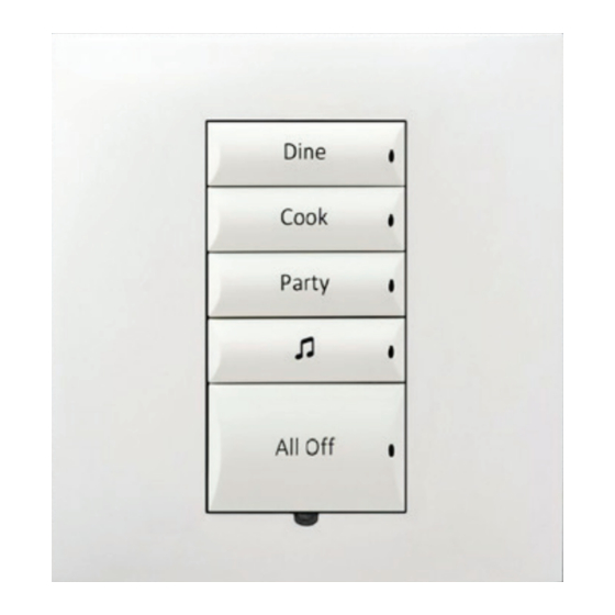
Square Wireless
Configurable Keypad
Installation Guide
Introduction
The Control4® Square Wireless Configurable Keypad is intended for use in a
Control4 system. It installs in a standard square (UK/China-style) or round (EU-
style) wall box using typical wiring standards and communicates to the Control4
system using a wireless connection.
Box contents
•
Square Wireless Configurable Keypad
•
Square Wireless Configurable Keypad Installation Guide (this document)
•
M3.5 machine screws (2)
•
M4.0 machine screws (2)
•
M3.0 thread-cutting screws (2)
Specifications
The specifications are described below.
Model number
Power requirements
Power consumption
Operational temperature
Humidity
Storage
Control communications
Wires per connector
Dimensions
Weight
Shipping weight
C4-SKC
120VAC-277VAC +/-10% 50/60 Hz 36-48VDC
This device requires a neutral AC connection except
when used in combination with a Control4 Dimmer in a
multi-location scenario.
120V: 350mW
240V: 480mW
277V: 540mW
36VDC: 430mW
Environmental
0˚C ~ 40˚C (32˚F ~ 104˚F)
5% to 95% non-condensing
-20˚C ~ 70˚C (-4˚F ~ 158˚F)
Miscellaneous
ZigBee, IEEE 802.15.4, 2.4 GHz, 15-channel spread
spectrum radio
One 0.5 mm
2
- 2.5 mm
2
(20AWG - 10AWG)
OR
2
2
Two 0.5 mm
- 1.5 mm
(20AWG - 16AWG)
83 × 71 × 17 mm (3.3 × 2.8 × 0.7 in)
0.05 kg (0.12 lb)
0.08 kg (0.18 lb)
Warnings and considerations
Warning! Turn OFF electrical power before installing or servicing this
product. Improper use or installation can cause SERIOUS INJURY,
DEATH or LOSS/DAMAGE OF PROPERTY.
Attention ! Coupez l'alimentation électrique avant d'installer ou de
réparer ce produit. Une mauvaise installation ou utilisation peut
entraîner des blessures graves, décès ou perte / dommages à la
propriété.
Warning! This device must be protected by a circuit breaker (20A max).
Attention ! Cet appareil doit être protégé par un disjoncteur (20A max.)
Important: When installing the keypad in a round wall box, a Trim
Ring (sold separately) must be installed between the keypad and the
wall box. Trim Rings are available in both single-gang and dual-gang
versions.
Important: This device must be installed by a licensed electrician in
accordance with all national and local electrical codes.
Important: Use this device only with copper or copper-clad wire. Do not
use aluminum wiring. This product has not been approved for use with
aluminum wiring.
Important: Using this product in a manner other than outlined in
this document voids your warranty. Further, Control4 is NOT liable
for any damage incurred with the misuse of this product. See
Important: Do NOT use a power screwdriver to install this device. If you
do, you may overtighten the screws and strip them. Also, overtightening
the screws may interfere with proper button operation.
Important: This is an electronic device with intricate components.
Handle and install with care!
Installation instructions
1 Ensure that the location and intended use meet the following criteria:
•
When replacing a traditional multi-way (cross) switch, refer to the "Two-
Location" sample wiring configurations provided in the appropriate load
control device installation guide.
•
Install in accordance with all national and local electrical codes.
•
The range and performance of the wireless control system is highly
dependent on the following: (1) distance between devices; (2) layout
of the home; (3) walls separating devices; and (4) electrical equipment
located near devices.
2 Turn off the mains electrical power at the consumer unit. To ensure the wires
do not have power running to them, use an inductive voltage detector.
3 Determine whether the keypad will be installed in a square or round wall
box. If the keypad is to be installed in a round wall box, ensure that the
appropriate trim ring (sold separately) is available before proceeding.
4 Prepare each wire. Wire insulation should be stripped back 7mm from the
wire end.
5 If installing in a round wallbox, pull the wires through the center hole in the
trim ring. The arrows on the trim ring should face forward and up.
6 Connect the keypad to the wall box wires as shown in Figure 1 below. (Refer
to the C4-SAPD240 Dimmer Installation Guide or the C4-SSW240 Switch
Installation Guide for multi-location wiring details.)
Figure 1: Keypad wiring
7 Fit the wires back into the wall box.
Line
L
N
Neutral
Advertisement
Table of Contents

Subscribe to Our Youtube Channel
Related Manuals for Control 4 C4-SKC


Summary of Contents for Control 4 C4-SKC
- Page 1 The specifications are described below. of the home; (3) walls separating devices; and (4) electrical equipment located near devices. Model number C4-SKC 2 Turn off the mains electrical power at the consumer unit. To ensure the wires Power requirements 120VAC-277VAC +/-10% 50/60 Hz 36-48VDC do not have power running to them, use an inductive voltage detector.
- Page 2 8 Follow the appropriate instructions for attaching the keypad: Figure 4: Round wall box installation—vertical screw holes To install in a square (UK/China-style) wall box: a Align the keypad to the wall box as shown in Figure 1 (note the UP orientation arrow on the keypad), then fasten the keypad to the wall box using the included M3.5 machine screws (UK-style wall box) or M4.0 machine screws (China-style wall box).
- Page 3 Additional resources The following resources are available for additional support: • Control4 Knowledgebase and forums • Control4 Technical Support • Control4 website: www.control4.com • Composer documentation available at ctrl4.co/docs For the latest version of this document, open this URL or scan the QR code on a device that can view PDFs.
- Page 4 control4.com | 888.400.4070 Copyright ©2016, Control4 Corporation. All rights reserved. Control4, the Control4 logo, the 4-ball logo, 4Store, 4Sight, Control4 My Home, and Everyday Easy are registered trademarks or trademarks of Control4 Corporation in the United States and/ or other countries. All other names and brands may be claimed as the property of their respective owners.
Need help?
Do you have a question about the C4-SKC and is the answer not in the manual?
Questions and answers