Advertisement
Quick Links
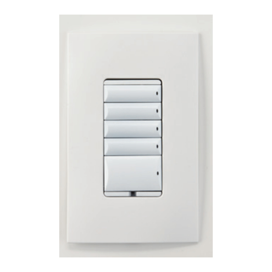
Fan Speed
Controller
Installation Guide
Supported Model
• C4-4SF120 Fan Speed Controller
Introduction
The Control4® Fan Speed Controller operates independently or as part of a
Control4 home automation system to provide four (4) quiet speeds plus an Off
setting for standard paddle-type ceiling fans. It installs in a standard back box
using typical wiring standards and communicates to the Control4 system using a
wireless connection.
Box Contents
• Fan Speed Controller
• Wire Nuts
• Warranty Card
• Fan Speed Controller Installation Guide (this document)
Specifications and Supported Load Types
The specifications are described below.
Model Number
C4-4SF120-xx
Power Requirements
120VAC +/-10%, 50/60Hz
This device requires a neutral connection. See
the "Sample Wiring Configurations" later in this
guide.
Power Consumption
500mW
Load Types and Ratings
Supported Load Types
Single, paddle-type ceiling fan
Maximum Load
2A
Environmental
Operational Temperature
32˚ F - 104˚ F (0˚ C - 40˚ C)
Humidity
5% to 95% non-condensing
Storage
-4˚ F - 158˚ F (-20˚ C - 70˚ C)
Miscellaneous
Control Communications
ZigBee, IEEE 802.15.4, 2.4 GHz, 15-channel
spread spectrum radio
Wallbox Volume
5.75 cubic inches
Weight
0.12 lb. (0.05 kg)
Shipping Weight
0.18 lb. (0.08 kg)
™
Warnings and Considerations
WARNING!
Turn OFF electrical power before installing or servicing this
product. Improper use or installation can cause SERIOUS INJURY, DEATH
or LOSS/DAMAGE OF PROPERTY.
ATTENTION!
Coupez l'alimentation électrique avant d'installer ou de
réparer ce produit. Une mauvaise installation ou utilisation peut entraîner
des blessures graves, décès ou perte / dommages à la propriété.
WARNING!
This device must be protected by a circuit breaker (20A max).
ATTENTION!
Cet appareil doit être protégé par un disjoncteur (20A max.)
WARNING!
Ground this device in accordance with the National Electric
Code (NEC) requirements. DO NOT rely solely upon the yoke plate's
contact with a metal back box for adequate grounding. Use the device's
ground wire to make a secure connection to the safety ground of the
electrical system.
ATTENTION!
Cet appareil doit être en conformité avec le Code national
de l'électricité (NEC). Ne comptez pas uniquement au contact de la
plaque avant avec un boîtier mural métallique pour la mise à la terre
adéquate. Utilisez cet appareil à la terre de l'appareil pour établir une
connexion sécurisée au système électrique.
IMPORTANT!
This device must be installed by a licensed electrician in
accordance with all national and local electrical codes.
IMPORTANT!
If you are unsure about any part of these instructions,
consult a qualified electrician.
IMPORTANT!
Use this device only with copper or copper-clad wire. Do
not use aluminum wiring. This product has not been approved for use with
aluminum wiring.
IMPORTANT!
Using this product in a manner other than outlined in this
document voids your warranty. Further, Control4 is NOT liable for any
damage incurred with the misuse of this product. See "Troubleshooting."
IMPORTANT!
Do NOT use a power screwdriver to install this device. If you
do, you may overtighten the screws and strip them. Also, overtightening
the screws may interfere with proper button operation.
IMPORTANT!
This is an electronic device with intricate components.
Handle and install with care!
Installation Instructions
1
Ensure that the location and intended use meet the following criteria:
• If the ceiling fan being controlled is a fan/light combination, there must be
separate load wires for the fan and light from the control location. A separate
Control4 dimmer or switch must be used if the light is to be controlled. Do
not use the Fan Speed Controller to control the light.
• Do not exceed the load capacity requirements of the Fan Speed Controller.
Refer to the load ratings in the specifications above for details.
• Install in accordance with all national and local electrical codes.
• The range and performance of the wireless control system is highly
dependent on the following: (1) distance between devices; (2) layout of the
home; (3) walls separating devices; and (4) electrical equipment located near
devices.
2
Turn off the local electrical power by either switching off the circuit breaker or
removing the fuse from the fuse box. To ensure the wires do NOT have power
running to them, use an inductive voltage detector.
NOTE:
The back box wiring shown in this document is an example. Your
wire colors and functions may differ. If you are not sure which wires
are the Hot, Neutral, Load, Traveler, and Ground wires, have a trained
electrician perform the installation.
3
Prepare each wire. Wire insulation should be stripped back 5/8 of an inch
from the wire end (see Figure 1).
Figure 1. Strip Wire Insulation
4
Identify your wiring application, and then see the appropriate wiring diagram
in the "Sample Wiring Configurations" section below.
IMPORTANT!
Not grounding this product, as described in the section
"Warnings and Considerations," may result in an installation less immune
to damage caused by electrical disturbances, such as ESD or lightning,
and may void the warranty.
5
Identify and connect the Fan Speed Controller wires to the back box wires
using the wire nuts.
IMPORTANT!
The yellow wire is not a traditional traveler. It cannot directly
power a load. It must be used only to connect to a Control4 Auxiliary
Keypad. See "Sample Wiring Configurations."
TIP:
If you are using a Control4 push-on (screwless) faceplate in a multi-
gang installation, attach the black faceplate sub-plate to all of the devices
that will be installed into the wallbox prior to attaching the devices to the
wallbox. This will help ensure that all the devices are properly aligned and
on the same plane after installation.
6
Fit the wires back into the back box. Bend the wires in a zigzag pattern so
that they easily fold into the back box (Figure 2).
Figure 2. Bend the Wires
7
Align the Fan Speed Controller to the back box (the load rating label should
be at the bottom) and fasten it with screws. Tighten the screws until the
back side of the yoke plate is even with the wall surface, but no further.
Overtightening can warp the dimmer and cause mechanical malfunction.
8
Install the Control4 Faceplate following the instructions in the Faceplate
Installation Guide or attach a standard Decora-style faceplate.
9
Turn ON power at the circuit breaker or replace the fuse
from the fuse box.
Operation and Configuration
On initial power up, all status LEDs on the Fan Speed Controller will illuminate
green indicating that the device has power. To set up the Fan Speed Controller for
use with a Control4 system, refer to the Composer Pro User Guide.
IMPORTANT!
If the fan speed can be adjusted via a pull chain, remote
control, etc., set the fan to high speed using that method prior to
operating with the Control4 Fan Speed Controller.
To operate the Fan Speed Controller as a stand-alone device:
• Click the top button to turn the fan on at high speed.
• Click the second button to turn the fan on at medium-high speed.
• Click the third button to turn the fan on at medium speed.
• Click the fourth button to turn the fan on at low speed.
• Click the bottom button to turn the fan off.
Button Tap Sequences
The button tap sequences are defined in the table below. Button tap sequences
that require a single (1) button should use the top button.
Function Sequence
Button
Identify
4
ZigBee Channel
7
Reboot
15
Factory Reset
9-4-9
Leave Mesh and Reset
13-4-13
Troubleshooting
If the fan does not turn on:
• Ensure at least one LED on the face of the Fan Speed Controller is lit.
• Ensure the light bulb is not burned out and is screwed in tightly.
• Ensure that the circuit breaker is not turned OFF or tripped.
• Check for proper wiring (see "Sample Wiring Configurations").
• For help on the installation or operation of this product, email or call the
Control4 Technical Support Center. Please provide your exact model number.
Contact support@control4.com or see the web site www.control4.com.
Care and Cleaning
•
Do NOT paint the Fan Speed Controller or its wall plate.
•
Do NOT use any chemical cleaners to clean the Fan Speed Controller.
•
Clean surface of the Fan Speed Controller with a soft damp cloth as needed.
Regulatory/Safety Information
To review Regulatory information for your particular Control4 products, see
the information located on the Control4 website at: http://www.control4.com/
regulatory/.
Patent Information
Applicable patents are available at http://www.control4.com/legal/patents.
Warranty
For complete warranty information, including details on consumer legal rights as
well as warranty exclusions, review the Warranty card or visit www.control4.com/
warranty.
About this Document
Part Number: 200-00313, Rev. A 3/02/2013
Advertisement

Related Manuals for Control 4 C4-4SF120 Series


Summary of Contents for Control 4 C4-4SF120 Series
- Page 1 ™ Warnings and Considerations IMPORTANT! Prepare each wire. Wire insulation should be stripped back 5/8 of an inch If the fan speed can be adjusted via a pull chain, remote control, etc., set the fan to high speed using that method prior to from the wire end (see Figure 1).
- Page 2 ™ Sample Wiring Configurations Figure 3. Single Device Location Figure 4. Multiple Device Location Using Auxiliary Keypad Figure 5. Multiple Device Location Using Configurable Keypad Copyright ©2013 Control4. All rights reserved. Control4, the Control4 logo, the Control4 iQ logo and the Control4 certified logo are registered trademarks or trademarks of Control4 Corporation in the United States and/or other countries.
- Page 3 Regulatory Compliance & Safety Information for Contol4 Model C4-SF120. Electrical Safety Advisory Sécurité électrique consultatif Important Safety Information Informations de sécurité importantes Read the safety instructions before using this product. Lisez les consignes de sécurité avant d'utiliser ce produit. 1. Read these instructions. Lisez ces instructions.
- Page 4 fournie pour votre sécurité. Si la fiche fournie ne s'adapte pas à votre prise, consultez un électricien pour le remplacement de la prise obsolète. 10. Protect the power cord from being walked on or pinched particularly at plugs, convenience receptacles, and the point where they exit from the apparatus. 10.
- Page 5 16. Pour couper entièrement l'alimentation appareil de l'alimentation secteur, éteignez le disjoncteur. Pour rétablir le courant, mettez le disjoncteur après les consignes de sécurité et des lignes directrices. 17. This product relies on the buildings installation for short-circuit (overcurrent) protection. Ensure that the protective device is rated not greater than: 20A.
- Page 6 Warning!: To reduce the risk of electrical shock, do not expose this apparatus to rain or moisture AVERTISSEMENT! Pour réduire le risque de choc électrique, n'exposez pas cet appareil à la pluie ou à l'humidité. Save these instructions Conservez ces instructions Compliance of this equipment is confirmed by the following label that is placed on the equipment: Conformité...
- Page 7 une installation particulière. Si cet équipement provoque des interférences nuisibles à la réception radio ou télévision, ce qui peut être déterminé en mettant l'équipement hors et sous tension, l'utilisateur est encouragé à essayer de corriger l'interférence par une ou plusieurs des mesures suivantes: ...
- Page 8 Cet équipement doit être installé par des professionnels qualifiés ou entrepreneurs conformément aux normes FCC partie 15.203 & IC RSS-210, Exigences d'antenne. Ne pas utiliser une antenne autre que celui fourni avec l'appareil. RF Radiation Exposure Statement This equipment complies with the FCC/IC radiation exposure limits set fourth for portable transmitting devices operation in an uncontrolled environment.