Table of Contents
Advertisement
Quick Links
Advertisement
Table of Contents

Related Manuals for Accusys TShare A16T3-Share


Summary of Contents for Accusys TShare A16T3-Share
- Page 1 A16T3-Share User Guide Accusys Storage Ltd., 2017 Version: V1.0...
- Page 2 Revision Sheet Release No. Date Revision Description V1.0 2017/8 Officially released.
- Page 3 Accusys Storage Ltd. All contents of this manual are copyrighted by Accusys Storage Ltd. The information contained herein is the exclusive property of Accusys Storage Ltd. and shall not be copied, transferred, photocopied, translated on paper, film, electronic media, or computer-readable form, or otherwise reproduced in any way, without the express written permission of Accusys Storage Ltd.
- Page 4 Preparing to Install Tshare A16T3-SHARE To ensure safe and smooth operation of your Tshare A16T3-SHARE, it is essential that you choose an appropriate location for the system, and provide an appropriate operating environment and adequate power for all components of the system. As you plan for installation, follow the guidelines below to ensure that the system and its environment are safely and appropriately positioned for efficient operation and service.
- Page 5 At your chosen location for the Tshare A16T3-SHARE, make sure that the electrical circuitry and power outlets are sufficient for the combined power needs of all hardware components. To plan for safe and adequate power to the system, follow these guidelines: 1.
-
Page 6: Table Of Contents
Table Of Content Introduce Shareable Thunderbolt RAID System .............. 8 What’s in the box ......................10 Introduce A16T3-Share ....................12 The front side of A16T3-Share ................13 Disk Mapping ....................14 LED indicator of disk tray ................. 14 The rear side of A16T3-Share ................15 Install A16T3-Share ...................... - Page 7 5.6.2 LUN Map ....................41 5.6.3 LUN Connect ..................41 5.6.4 Expansion ..................... 42 5.6.5 Migrations ..................... 43 5.6.6 Snapshot....................45 5.6.7 Health Center ..................49 5.6.8 Unlock Drives ..................50 Update the RAID System Firmware ..............52 Download Controller Log .................. 53 Disk RW Test ....................
-
Page 8: Introduce Shareable Thunderbolt Raid System
Introduce Shareable Thunderbolt RAID System... - Page 9 Accusys has leveraged its years of experience as a PCIe SAN designer and high performance transmission technology provider in the video post-production industry, and created the all-in-one A16T3-Share Thunderbolt shareable storage solution, which takes the original peer to peer Thunderbolt interface and transforms it into a more flexible Thunderbolt storage network well suited for Media and Entertainment budgets and workflows.
-
Page 10: What's In The Box
What’s in the box... - Page 11 Item Name Description Disk tray Disk tray x16 Rail set Hold up A16T3-Share in rack x2 Packing list Packing list Manual/Driver/GUI/Firmware files Power cord AC power cord x2 Rail Extender Extend RAID system from rack x2 Screws pack For installing disk x2 Bolts pack For installing to rack x6 Power converter...
-
Page 12: Introduce A16T3-Share
Introduce A16T3-Share... -
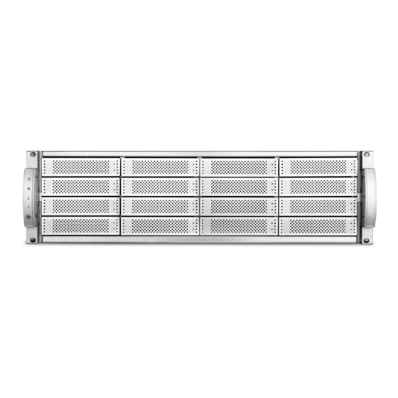
Page 13: The Front Side Of A16T3-Share
3.1 The front side of A16T3-Share Item Name Description Steady Blue controller is working normally Controller Flashing Blue host is accessing Status controller failed fan modules are working Blue normally System Fan fan module failed Blue system temperature is normal System Temperature system temperature is overheat... -
Page 14: Disk Mapping
3.2 Disk Mapping Disk 1 Disk 5 Disk 9 Disk 13 Disk 2 Disk 6 Disk 10 Disk 14 Disk 3 Disk 7 Disk 11 Disk 15 Disk 4 Disk 8 Disk 12 Disk 16 3.3 LED indicator of disk tray Disk Status LED #1 LED #2... -
Page 15: The Rear Side Of A16T3-Share
3.4 The rear side of A16T3-Share No. Name Description RAID controller The controller of RAID system Redundant SMART speed control Power Supply 100-240V 400W Redundant power module... - Page 16 No. Name Description Heart beat LED Flashing green indicates it works normally. Thunderbolt 3 host port 1(Left)~ 4 LED1 Blue Data access status Thunderbolt port LED2 Green Link status Debug port For engineer debugging only. T-Share Expansion Setting the chassis to be Master or Slave switch Expanding to another JBOD enclosure.
-
Page 17: Install A16T3-Share
Install A16T3-Share... -
Page 18: Rail Set Installation
4.1 Rail set installation A16T3-Share is designed as standard 19inch 3U chassis, support all standard rack. Follow the steps to properly install you RAID system into rack. 1. Loosen rail screws of rail set, and adjust 2. Tighten 2 rack screws in both front and the length to fit your rack rear side. -
Page 19: Installing Disk Drives
4.2 Installing Disk Drives 1. Place the drives with connector align with the edge of the disk tray and secure drive with screws as below figures. Four screws for 3.5” Three screws for 2.5” 2. Push the tray inward until the tray firmly connects and you hear the tray click into place. -
Page 20: Connecting Jbods
4.3 Connecting JBODs A16T3-Share support JBOD expansion, you can expand the capacity via connecting up to 3 A16S3-SJ JBOD enclosure. Follow the steps below to connect JBODs; 1. Use mini SAS HD cable (equipped in A16S3-SJ accessory package) to connect the “EXP”... -
Page 21: Installing Driver And Gui On Host
Installation files can be found in installation USB, or you can download the latest version from our website (http://www.accusys.com.tw/support/download.html). If you need further technical support, please contact your reseller or Accusys support team. (see chapter “Customer Service and Technical Support” for more information) 1. -
Page 22: Connecting Host Port
4.5 Connecting Host Port A16T3-Share supports four Thunderbolt 3 and one PCIe 3.0 host ports, depends on your plan, you can create multiple arrays for dedicated host or create an array be visible by all hosts to build a SAN environment, Follow the steps below to setup a host connection, 1. -
Page 23: T-Share Expansion
4.6 T-Share Expansion By utilizing T-Share Expansion, users are able to pair two A16T3-Share devices doubling the available Thunderbolt 3 ports to eight. Each port provides rapid transfer speeds and allows large workgroups to simultaneously collaborate on projects with extreme workflow efficiency. Requirement - Two A16T3-Share RAID systems - PCIe cable... -
Page 24: T-Pairing
T-pairing allows for the use of multiple ports to experience enhanced performance. T-pairing is protocol independent and all T-share devices are pre-installed with Accusys Mac Installer which includes the driver for T-Pairing. Once the driver is installed it will automatically communicate with the T-Share RAID controller for easy configuration. - Page 25 Follow the steps in this chapter to enable T-Pairing. Requirement - RAID System code must be version 3.5.2 or later - Accusys Installer must be version 3.5.2 or later - Host must equip two Thunderbolt ports on independent Thunderbolt bus (Not daisy-chain).
-
Page 26: Raidguardx
RAIDGuardX... -
Page 27: Raidguardx Overview
5.1 RAIDGuardX Overview RAIDGuardX support local and remote monitoring of multiple controllers that are connected to the same network, which consist of 2 components: RAIDGuardX-Server and RAIDGuardX-Client. RAIDGuardX-Client: A java-based console for managing and monitoring RAID system. RAIDGuardX-Server: RAIDGuardX-Server is an agent service in charge of communication between RAIDGuardX-Client and RAID controller;... -
Page 28: Raidguardx Main Console
5.1.2 RAIDGuardX Main Console Function Description Add controller into RAIDGuardX (for DAS only) Monitoring Buttons Remove controller from RAIDGuardX Create array in the RAID system Delete array in the RAID system Email to set email notification Drive Lag Proof Enable/ Disable NCQ mode Enable/ Disable SMART Mode Enable/ Disable Preference... -
Page 29: Add/Remove Controller
5.2 Add/Remove Controller RAIDGuardX can manage the RAID controller locally or remotely via intranet access. 5.2.1 Add Controller 1. Open RAIDGuardX-Client, you may add controller by locally or remotely; Locally: Click Add Controller to display a list of available controllers Remote: Click Controller tab >... -
Page 30: Create/Delete An Array
5.3 Create/Delete an Array This chapter will guide you how to use RAIDGuardX to create/delete disk array. 5.3.1 Create Array 1. Click icon Create Array, then create array page will pop up as below, Note 1. Check LUN assign automatically and you can select host port. - Page 31 4. Click on the drive icon or Select all spare drivers to select all available drives. Note Unselected drive will be set to Hot (Global) spare drive. If an array member drive fails, spare drive will start to rebuild automatically. Click the initialization type: On-the-fly initialization or Performance evaluation.
-
Page 32: Delete An Array
Note A16T3-Share can support up to 5 array groups. 5.3.2 Delete an Array 1. Click icon Delete Array on RAIDGuardX, to pop up a dialog as below picture 2. Click on the drive icon of the array to be deleted. 3. -
Page 33: Email Notification
5.4 Email Notification It may be necessary for network administrators to receive e-mails in the event of errors, alerts, and changes to the RAID array. These alerts can be e-mailed to a maximum of 20 e-mail addresses. 1. Mailing List Enter the e-mail address of people to receive controller error reports. -
Page 34: Preference
5.5 Preference 5.5.1 Disk Lag Proof This feature ensures the stability and continuity of the RAID performance. In RAID 5 and RAID 6, DLP prevents the aging or slow responds of a single hard disk from influencing the overall performance. The advantage of this feature is making sure the data be protected if some hard disks fail to perform well. -
Page 35: Ncq
5.5.3 SMART Mode S.M.A.R.T. is a monitoring system of disk drives to detect and report on various indicators of reliability, in the hope of anticipating failure. Accusys RAID system supports S.M.A.R.T. Once this function is selected, you can select the check interval from the drop-down list. -
Page 36: Beeper
5.5.4 Beeper To enable/disable system beeper, default is enabled. 5.5.5 Equalization Mode Regardless the transmission method, the data transmission speed cannot be guaranteed at all times. This feature allows the continuous I/Os to operate more smoothly and substantially reduce large fluctuations in efficiency during data transfer. For video editing, enable equalization to prevent video frame drops. -
Page 37: Cache
5.5.6 Cache In this section, cache of RAID controller and drive can be configured by manual; default setting is tuned for video streaming application. Controller Cache – Check this box to enable the controller cache. This speeds up the data transfer to and from the disks. Caution Data in cache may be erased if power down unexpected. -
Page 38: Misc
Note: If you forget your password, you will have to contact your agent or the Accusys Support Team. SNMP Notification – Select SNMPv1 or SNMPv2 to send notifications for error conditions and possible problems to the SNMP servers. SNMP stands for Simple Network Management Protocol. -
Page 39: Slicing
5.6 Option 5.6.1 Slicing RAID slicing overcomes the inherent design of how data is stored on a drive or RAID system by subdividing a RAID array into segments, or slices. These slices are effective hardware partitions of all drives in the array. Each slice is a separate LUN and appears as a separate volume on the host computer. - Page 40 Usage Scenario: The access speed of the data stored in the outer circle is faster than the inner circle. Suppose there are two slices in a hard drive, Slice 0 locates in the outer circles while Slice 1 in the inner circle, for audio/video editing, you may store video Follow the steps below to select an array to slice or merge.
-
Page 41: Lun Map
5.6.2 LUN Map LUN, which stands for Logical Unit Number, is used to identify a logical unit in computer storage. When creating an array, you may select Assign LUN automatically to automatically assign a LUN to the new array. If Assign LUN automatically is not selected, you need to assign the LUN manually using LUN map. -
Page 42: Expansion
2. Select a LUN in Select LUN area 3. Check the Confirm box and click OK. 4. Repeat the steps to create more LUN Connect if need. Note LUN Map must be set and then you can set LUN Connect. 5.6.4 Expansion Expansion adds spare disk to an existing array. -
Page 43: Migrations
5.6.5 Migrations Different from Expansion, which enlarges an array by adding hard drives to a fixed RAID level, Migration changes the RAID level of an array. It allows live changes to the RAID without the need to delete the array and rebuild. This can be useful when new drives have been added, and a new array type needs to be created. - Page 44 1. Select the array to migrate. From the drop down menu, select the RAID level to migrate to, and then select the total number of drives to include in the array. A “+” appears above the drive(s) to be added, and a “-” sign above the drive(s) to be removed.
-
Page 45: Snapshot
5.6.6 Snapshot A snapshot is initialized with a data duplicate from a source to a target. The mirror snapshot is offered by the ExaSAN RAID controller. Note The source and target volume of the snapshot must be identical. Before setting a snapshot, you need to set the slice in the array. The capacity of each slice and the number of shots should be in accordance with the space you need. - Page 46 Delete Shot Delete the selected shot. 1. Select the Delete Shot function from the drop down menu. 2. Select the required shot by clicking on the Shot No. radio button. From the respective drop down menus, select the source volume and destination volume. Unavailable shots are grayed out.
- Page 47 1. Select the Split Shot function from the drop down menu. 2. Select the Split Scheduling radio button. 3. Click on the time and date button to set split time. 4. Select the required shot by clicking on the Shot No. radio button. From the respective drop down menus, select the source volume and destination volume.
- Page 48 2. Select the required shot by clicking on the Shot No. radio button. You can only select split shot for resynchronization. 3. Check the Confirm box and click OK to split the snapshot. Note 1. The destination volume must be equal or larger in size than the source volume.
-
Page 49: Health Center
5.6.7 Health Center To ensure the accuracy of the RAID parity data, RAID controller offers Background checking and “Rebuild parity data.” During checking or rebuilding parity, the performance of the array will be affected. You could check the progress in the Main view or in the Health Center. -
Page 50: Unlock Drives
5.6.8 Unlock Drives The RAID controller may lock abnormal drives in an array. You may unlock these drives and rejoin them in an array. Drives may be locked with one of two conditions: 1. If a drive returns data too slowly, the controller will determine the drive is experiencing a failure and execute Drive Drop. - Page 51 1. Select the drive with the icon. It will change to the icon. 2. Check the Confirm box and click Unlock Drive.
-
Page 52: Update The Raid System Firmware
Follow the steps in this section to update the firmware of your RAID system. Note the current firmware version (System Code, Boot Code, Expander Code, etc) from RAIDGuardX. Download the latest firmware from website www.accusys.com.tw/support/download.htm. Caution - Do NOT writing data, shutdown, interrupt RAID system during updating, in order to avoid any damage. -
Page 53: Download Controller Log
(zip) will be saved at RAIDGuardX installed folder, Note Default folder to save zipped log file, MAC: /Application/RAIDGuardX/Log Windows: /Program Files/Accusys/RAIDGuardX/Log Linux: /{RAIDGuardX-Client folder}/RAIDGuardX/Log 5.9 Disk RW Test Read/Write throughput is highly depending on the condition of disk inserted in RAID system. - Page 54 2. Click Yes on dialog window 3. Display test result on Event page Spare disks Array Member disks...
-
Page 55: Raid Overview
RAID Overview... -
Page 56: How Raid Works
Scalability for expansion of storage. Accusys RAID systems use a hardware controller to manage multiple drives as one or more RAID array group, which offloads RAID task from host, and provides independent, fast and highly efficient storage. The way of controller stores and retrieves data on the RAID system is determined by the RAID level and storage method you choose. -
Page 57: Raid 0: Striping
6.2.1 RAID 0: Striping RAID level 0, striping only, is the fastest and most efficient array type, but offer no fault-tolerance. Any drive failure will destroy the data in the array. 6.2.2 RAID 1: Mirroring RAID level 1, mirroring, each drive stores identical data. RAID 1 provides very high data reliability and improved performance for read-intensive applications, but this level has a high capacity cost because it retains a full copy of your data on each drive in the mirror set. -
Page 58: Raid 6: Independent Data Disks With Two Independent Parity Schemes
6.2.4 RAID 6: Independent Data Disks with Two Independent Parity Schemes RAID level 6 extends RAID level 5 by adding an additional parity block; thus it uses block-level striping with two parity blocks distributed across all member disks. RAID 6 allows two of the array member disks to have failures at the same time and keeps the storage working. - Page 59 Total Capacity RAID Data Minimum (N = number of Redundancy Performance Level Format Drive drive) RAID0 Stripe Single Drive * N None High RAID1 Mirror Single Drive * 1 N – 1 Stripe with Single Drive * RAID5 Medium 1 Parity (N-1) Stripe with Single Drive *...
-
Page 60: Appendix
Appendix... -
Page 61: Appendix A: Faqs
4. Q: Insert a drive, RAID system start warning with 3 short beeps, the drive’s status is locked on RAIDGuardX, why? A: The drive could be initialized in other Accusys product and it contains a portion of a RAID configuration and data. If the data isn’t important you can unlock the drive in GUI>Options>Unlock. - Page 62 6. Q: RAID system alerts 3 short beeps repeatedly, what does it mean? A: Error could be related to Fan, Power, RAID controller module, or there is a disk been locked. Refer to below table of Beeper Code for more detail. Beeper mode Description 1 short beep (boot up)
-
Page 63: Appendix B: Customer Service And Support
2) Host operation system log with RAID related error. B.2 Contact Us Email us for customer services and technical support; Sales: sales@accusys.com.tw Technical Support: support@accusys.com.tw B.3 Website Please visit our websites frequently for the most up-to-date product and support information.
Need help?
Do you have a question about the TShare A16T3-Share and is the answer not in the manual?
Questions and answers