
Subscribe to Our Youtube Channel
Related Manuals for PROLiNK IPS Series


Summary of Contents for PROLiNK IPS Series
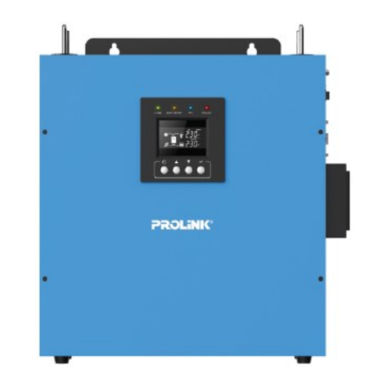
- Page 1 OFF-GRID SOLAR INVERTER User Manual IPS SERIES – TOWER/DESKTOP/WALL MOUNT IPS3003-P/M & IPS5003-P/M 3KVA/5KVA Version 1.00 (English)
-
Page 2: Table Of Contents
Table of Contents SAFETY INSTRUCTIONS ....................... 2 PRODUCT OVERVIEW ........................3 PRODUCT OUTLOOK ........................3 INSTALLATION ..........................5 OPERATION ............................ 8 TROUBLE SHOOTING ........................16 SPECIFICATION ..........................17 DIPOSAL ............................18... -
Page 3: Safety Instructions
SAFETY INSTRUCTIONS Before using the product, please read carefully the warning messages and instructions on labels and user manual of this product and other components connected to the product. This product is designed to be connected with lead-acid battery only. Do not connect the product with other types of battery. To reduce risk of damage and injury, please use batteries with good quality. -
Page 4: Product Overview
PRODUCT OVERVIEW This is a DC-to-AC inverter, which can be used as a long run-time UPS (Uninterruptible Power Supply), an energy-saving solution or an automotive inverter (hereinafter referred to as “inverter”). The inverter accepts input power source from AC mains (utility), battery and PV (solar) string and switches between various operation modes automatically depending on the operational conditions. - Page 5 Rear Panel 1. DC input terminals 2. AC input terminals 3. AC output terminals 4. PV input terminals 5. AC input breaker 6. P ower on/off button 7. RS-232 communication port...
-
Page 6: Installation
INSTALLATION Unpacking and Inspection This product package include following items. Please call your supplier or dealer if any items are missing. 1 X Inverter 1 X User’s manual 2 X Setting screws Safety Clearance The minimum clearance to the wall shall be larger than 30cm in order to ensure proper ventilation. In the event the ambient temperature is high, it’s recommended to increase the distance of safety clearance to improve the heat dissipation. - Page 7 While connecting multiple batteries, use the same brand/type for all batteries. Do not mix the battery bank with different brand/type of batteries. The user may connect the batteries in series in order to double the voltage connected to inverter. The diagram below illustrate how to connect two 12V batteries in series to make up 24V (for 3000VA model) and four 12V batteries in series to make up 48V (for 5000VA model) PV (solar) string Selection of PV Panel...
- Page 8 Connect the PV strings As the PV string generates power as long as illumination exists, a circuit breaker shall be installed between the PV string and inverter so that the power from PV string can be switched off when needed (e.g. regular maintenance) Connect the cables from PV string to PV input terminals as shown below.
-
Page 9: Operation
OPERATION After connecting batteries, AC input cables, and loads, the inverter is now ready to work. Power on/off Once the inverter has been properly installed, press the power switch to turn on the unit. The unit will work automatically in line mode or inverter mode according to input utility power’s status. - Page 10 Icon Function Input source information Indicates utility power Indicates the PV power Configuration Program and Fault Information Indicates the setting programs Indicates the warning and fault codes Indicates mute Indicates standby mode Indicates power on mode Other Information Indicates input, output, PV and battery information Battery Level Indicates battery level in battery mode and charging status.
- Page 11 Function LCD Display Options Default Description Buzzer is enable default, you can set it Buzzer on Buzzer enable disable to turn off alarm sounding. If select Hi, AC input voltage will be within Hi(wide) AC input voltage 90-280VAC. Lo(narrow) If select Lo, AC input voltage will be within range 170-280VAC.
- Page 12 If setting “Both”, the solar power and utility power charging the battery together.(default) If setting “Utility”, the utility power charging the battery first. Solar energy will charge battery only when utility power is not Charger Source available. priority If setting “PV”, the solar power charging the battery first.
- Page 13 Max charging current: To configure total charging current for solar and utility 10/20/30/40/50/60/70/ Max. charging current=utility 80/90 /100A charging current + solar chargers:(Max charging current charging current=utility charging current + solar charging current) If setting value in 008 is smaller Maximum AC 10/20/30/40A than that in 009, the inverter will...
- Page 14 Operating Mode Description Operating mode LCD Display Utility input bypass to output, and charge the battery. Standby charging mode Battery can be charged without switching on the unit. Battery is charging by PV energy only, no AC output. Utility input bypass to output, and charging by both utility and PV. 8 13...
- Page 15 Utility input bypass to output, and battery can be charged when Line mode switching on the unit. Utility input bypass to output, and battery can be charged by both utility and PV when switching on the unit. Battery mode The backup power to load comes only from battery. The backup power to load comes from battery and PV energy.
- Page 16 Fault and warning code Fault Code Event Audible Alarm Overload Rapid beeping every 1/2 second High Temperature Beep every second PV Voltage High Beep every second PV Current High Beep every second PV Charger NTC Disconnect Beep every second Output Voltage High Constant tone Output Short Constant tone...
-
Page 17: Trouble Shooting
TROUBLE SHOOTING Problem Possible Cause Remedial Action Re-charge the battery and check if the Battery voltage is low battery cables are well-connected No LCD display Battery is defective Replace the batteries Power button is not pressed Press and hold the power button Mains are normal but works in backup Check the connection of AC input AC input is absent... -
Page 18: Specification
SPECIFICATION Model CAPACITY VA/W 3000VA/2400W 5000VA/4000W NOMINAL BATTERY VOLTAGE 24Vdc 48Vdc LINE MODE INPUT Nominal Voltage 220/230/240Vac Voltage Range Wide mode: 90VAC-280VAC(default) Narrow mode: 170VAC-280VAC Normal Frequency 50/60Hz OUTPUT Voltage 220/230/240Vac Frequency Follow the Utility Output Waveform Follow the Utility EFFICIENCY >96%(full R load, battery full charged) TRANSFER TIME... -
Page 19: Diposal
DIPOSAL In the event the product reaches the end of its service life, please contact the local dealer for disposal instructions. The product must not be disposed of with the household waste. Disposal of the product at the end of its service life shall be done in accordance with applicable regulations for electronic waste. - Page 20 Register Online For Your Product Warranty @ www.prolink2u.com/register PROLiNK® is a trademark of FIDA INTERNATIONAL (S) PTE LTD and is manufactured under its authority. All other brands, products, services, logos and company names mentioned herein are trademarks of their respective owners.
Need help?
Do you have a question about the IPS Series and is the answer not in the manual?
Questions and answers