System Sensor OSI-RE-SS Quick Start Manual
Smoke detection system
Hide thumbs
Also See for OSI-RE-SS:
- Installation and maintenance instructions manual (17 pages) ,
- Quick start manual (29 pages)
Table of Contents
Advertisement
Quick Links
QUICK START GUIDE
OSI-RE-SS
Smoke Detection System
SPECIFICATIONS
Wire Gauge for Terminals:
Operating Voltage Range:
Maximum Standby Current:
Maximum Alarm Current (LED on): 11 mA @ 32 VDC, 15 mA @ 24 VDC, 24 mA @ 12 VDC, 54 mA @10.2 VDC
Operating Humidity Range:
Operating Temperature Range:
Application Temperature Range:
Adjustment Angle:
Sensitivity Levels:
Fault Condition (Trouble):
Alignment Aid:
Alarm Indicator:
This guide provides information on how to install the OSI-RE-SS Smoke Detec-
tion System.
Extensive product and critical product security information can be found
in the OSI-RE-SS Installation Guide (Document No. E56-6654) available at
www.systemsensoreurope.com/products/category/beam-smoke-detectors/.
The OSI-RE-SS system consists of an Imager and a reflector.
The products shall be powered from a EN54-4 certified AC/DC Power convert-
ers to be in compliance for CE certification.
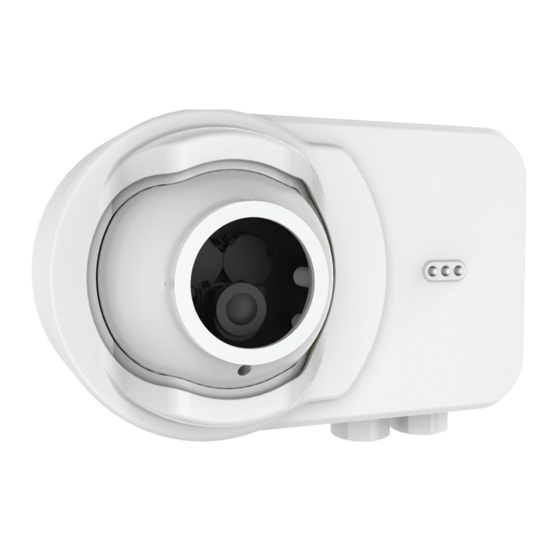
FIGURE 1. IMAGER AND REFLECTOR
DETERMINE THE POSITIONS OF THE IMAGER AND REFLECTOR
COMPONENTS
Make sure that the intended mounting locations meet the following criteria
(See Figure 2.):
• Detector spacing must comply with local codes and standards
• Reflector must be located within the Field of View (FOV) of the Imager
• Clear path between the reflector and Imager
• Mounted well above the head-height of people and obstructions
• Avoid direct sunlight onto the units
The Imager and reflector should be placed within a recommended distance
below the ceiling. (See Figure 3.) This value will vary according to regional
specifications, geometry, and specific requirements for the installation. The
distance for flat ceilings and basic spacing requirements (S) is shown in the
following table.
Standard
Distance from Ceiling
NFPA 72
300 mm (12 in.) minimum
AS1670.1
25 to 600 mm (1 to 23.6 in.)
BS5839.1
25 to 600 mm (1 to 23.6 in.)
GB50166
300 to 1000 mm (11.8 to 39.4 in.)
22 AWG (0.64 mm, 0.34 mm
2
) to 14 AWG (1.6 mm, 2.08 mm
10.2 to 32 VDC (12 or 24VDC nominal)
7 mA @ 32 VDC, 11 mA @ 24 VDC, 20 mA @ 12 VDC, 50 mA @ 10.2 VDC
0% to 95% Relative Humidity, Non-condensing
UL-Listed for use from 32°F to 100°F (0°C to 37.8°C)
20°C to +55°C (-4°F to 131°F)
20 degrees vertical, 50 degrees horizontal
Level 1 25%, Level 2 30%, Level 3 40%, Level 4 50% Automatically set at start up
Long-term drift reference out of 20% range, beam blockage or detector out of alignment, imager saturated.
LED directional arrows
Local red LED and remote output
C2051-00, C2052-00
Maximum Spacing (S)
18.3 m (60 ft)
14 m (45.9 ft)
15 m (49.2 ft)
14 m (45.9 ft)
2
)
For full information on spacing requirements, please refer to your local codes
and standards.
FIGURE 2. MOUNTING LOCATIONS
1/2 S
12" minimum
(0.3m)
30' (9.1m) maximum
To First
Detectors
10' (3.0m)
Wall
minimum
Typical
FIGURE 3. MOUNTING LOCATIONS
Ex. Distances according to NFPA 72 (S524 in Canadian applications).
Tx/Rx
1/4 S
maximum
Tx/Rx
1
Pittway Tecnologica S.r.l.,
Via Caboto 19/3,
34147 TRIESTE, Italy
S
1/2 S maximum
Reflector
S
Reflector
16 ft. (5m) minimum
328 ft. (100m) maximum
I56-6654-000
13/10/2020
C2053-00
C2054-00
Advertisement
Table of Contents

Related Manuals for System Sensor OSI-RE-SS


Summary of Contents for System Sensor OSI-RE-SS
- Page 1 Alignment Aid: LED directional arrows Alarm Indicator: Local red LED and remote output This guide provides information on how to install the OSI-RE-SS Smoke Detec- For full information on spacing requirements, please refer to your local codes tion System. and standards.
- Page 2 MOUNT THE REFLECTOR USING THE DRILL TEMPLATE FIGURE 5. WIRING THE TERMINATION CARD Refer to Appendix II. in Installation guide for drill template instructions. MOUNTING THE DETECTOR Remove detachable front rim cover. To detach the Imager part from the backbox, loosen the 3 holding screws. Fault NO Fault COM To provide cable access to the Termination Card of the Imager remove the...
- Page 3 FIGURE 7. OSI-RE-SS TERMINALS FIGURE 10. ARROW ARRAY RTS151/Key Terminals OSI-RE-SS Terminals Remote Alarm Output T2-1 Remote Trouble Output T2-2 T2-3 Remote Test/Reset Input External AUX - Jumper T2-4 C2061-00 FIGURE 11. LOCKING AND SECURING EYE BALL 10k ohm External...
- Page 4 DISCLAIMER Please refer to the insert for the Limitations of Fire Alarm Systems. For warranty terms, please refer to the Product Guide found at www.systemsensoreurope.com/products/category/beam-smoke-detectors/. System Sensor® is registered trademarks of Honeywell International Inc. I56-6654-000 ©2020 System Sensor. 13/10/2020...
Need help?
Do you have a question about the OSI-RE-SS and is the answer not in the manual?
Questions and answers