Table of Contents
Advertisement
Quick Links
www.ti.com
User's Guide
INA296EVM
This user's guide describes the characteristics, operation, and use of the INA296EVM evaluation module (EVM).
This EVM is designed to evaluate the performance of the INA296A or INA296B voltage-output, current shunt
monitor in a variety of configurations. Throughout this document, the terms evaluation board, evaluation module,
and EVM are synonymous with the INA296EVM. This document also includes a schematic, reference printed
circuit board (PCB) layouts, and a complete bill of materials (BOM).
SBOU280 – MARCH 2022
Submit Document Feedback
ABSTRACT
Copyright © 2022 Texas Instruments Incorporated
INA296EVM
1
Advertisement
Table of Contents

Subscribe to Our Youtube Channel
Related Manuals for Texas Instruments INA296EVM


Summary of Contents for Texas Instruments INA296EVM
- Page 1 INA296EVM ABSTRACT This user’s guide describes the characteristics, operation, and use of the INA296EVM evaluation module (EVM). This EVM is designed to evaluate the performance of the INA296A or INA296B voltage-output, current shunt monitor in a variety of configurations. Throughout this document, the terms evaluation board, evaluation module, and EVM are synonymous with the INA296EVM.
-
Page 2: Table Of Contents
Table of Contents www.ti.com Table of Contents 1 General Texas Instruments High Voltage Evaluation (TI HV EVM) User Safety Guidelines..........Overview....................................4 2.1 EVM Kit Contents................................4 2.2 Related Documentation From Texas Instruments......................3 Hardware....................................3.1 Features..................................... Operation....................................6 4.1 Quick Start Setup................................ -
Page 3: General Texas Instruments High Voltage Evaluation (Ti Hv Evm) User Safety Guidelines
General Texas Instruments High Voltage Evaluation (TI HV EVM) User Safety Guidelines 1 General Texas Instruments High Voltage Evaluation (TI HV EVM) User Safety Guidelines WARNING Always follow TI’s setup and application instructions, including use of all interface components within their recommended electrical rated voltage and power limits. -
Page 4: Overview
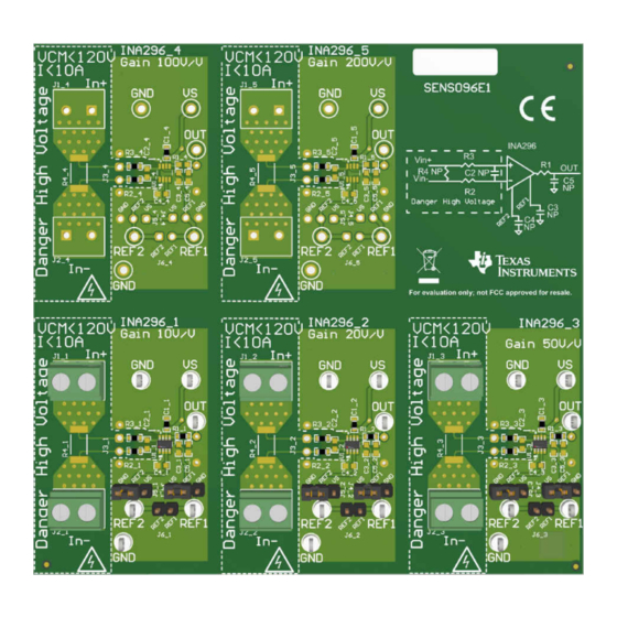
Overview www.ti.com 2 Overview The INA296EVM device is a voltage-output, high-side current sense amplifier in a small SOT-23 (8) package with high small signal bandwidth of 1 MHz for all gain options. As shown in Table 2-1, the INA296x has gains that range from 10 V/V to 200 V/V, depending on the gain option that is selected. -
Page 5: Hardware
Hardware 3 Hardware The INA296EVM provides a basic functional evaluation of the INA296x. The fixture layout is not intended to be a model for the target circuit, nor is it laid out for electromagnetic compatibility (EMC) testing. The INA296EVM is... -
Page 6: Operation
4 Operation 4.1 Quick Start Setup Follow these procedures to set up and use one of the INA296EVM panels. For these instructions, n is gain option 1, 2, 3, 4, or 5. 1. Choose the desired gain option panel variation. -
Page 7: Evm Components
EVM Components 5 EVM Components This section summarizes the INA296EVM components. For these instructions, n is gain option 1, 2, 3, 4, or 5. 5.1 R1_n, R2_n, R3_n, C2_n, C5_n R1_n, R2_n, and R3_n are factory-installed 0-Ω 0603 resistors. -
Page 8: Schematic, Pcb Layout, And Bill Of Materials
6.1 Schematics Figure 6-1 shows the schematic for one of the gain panels on the INA296EVM PCB. All other panels will have reference designators as subscript "_x" where "x" is the gain option. Figure 6-1. INA296EVMEVM Schematic: Gain Option 1 Panel INA296EVM SBOU280 –... -
Page 9: Pcb Layout
Schematic, PCB Layout, and Bill of Materials 6.2 PCB Layout Figure 6-2 through Figure 6-8 show the PCB layout for the INA296EVM. Figure 6-2. INA296EVM Top Overlay Figure 6-3. INA296EVM Bottom Overlay Figure 6-4. INA296EVM Top Layer Figure 6-5. INA296EVM Bottom Layer SBOU280 –... -
Page 10: Figure 6-6. Ina296Evm Top Solder
Schematic, PCB Layout, and Bill of Materials www.ti.com Figure 6-6. INA296EVM Top Solder Figure 6-7. INA296EVM Bottom Solder Figure 6-8. INA296EVM Drill Drawing INA296EVM SBOU280 – MARCH 2022 Submit Document Feedback Copyright © 2022 Texas Instruments Incorporated... -
Page 11: Bill Of Materials
Schematic, PCB Layout, and Bill of Materials 6.3 Bill of Materials Table 6-1 provides the parts list for the INA296EVM. Table 6-1. Bill of Materials Designator Value Description Package Reference Part Number Manufacturer C1_1, C1_2, C1_3, C1_4, C1_5 0.1uF CAP, CERM, 0.1 µF, 50 V,+/- 10%, X7R, AEC-Q200 Grade 1,... - Page 12 Keystone Electronics TP3_4, TP3_5, TP4_4, TP4_5, TP5_4, TP5_5, TP6_4, TP6_5 U1_4, U1_5 -4-V to 110V, Bidirectional, 1-MHz, 5V/μs, Ultra-Precise Current SOT-23-8 INA296A1IDDF Texas Instruments Sense Amplifier INA296EVM SBOU280 – MARCH 2022 Submit Document Feedback Copyright © 2022 Texas Instruments Incorporated...
- Page 13 STANDARD TERMS FOR EVALUATION MODULES Delivery: TI delivers TI evaluation boards, kits, or modules, including any accompanying demonstration software, components, and/or documentation which may be provided together or separately (collectively, an “EVM” or “EVMs”) to the User (“User”) in accordance with the terms set forth herein.
- Page 14 www.ti.com Regulatory Notices: 3.1 United States 3.1.1 Notice applicable to EVMs not FCC-Approved: FCC NOTICE: This kit is designed to allow product developers to evaluate electronic components, circuitry, or software associated with the kit to determine whether to incorporate such items in a finished product and software developers to write software applications for use with the end product.
- Page 15 www.ti.com Concernant les EVMs avec antennes détachables Conformément à la réglementation d'Industrie Canada, le présent émetteur radio peut fonctionner avec une antenne d'un type et d'un gain maximal (ou inférieur) approuvé pour l'émetteur par Industrie Canada. Dans le but de réduire les risques de brouillage radioélectrique à...
- Page 16 www.ti.com EVM Use Restrictions and Warnings: 4.1 EVMS ARE NOT FOR USE IN FUNCTIONAL SAFETY AND/OR SAFETY CRITICAL EVALUATIONS, INCLUDING BUT NOT LIMITED TO EVALUATIONS OF LIFE SUPPORT APPLICATIONS. 4.2 User must read and apply the user guide and other available documentation provided by TI regarding the EVM prior to handling or using the EVM, including without limitation any warning or restriction notices.
- Page 17 Notwithstanding the foregoing, any judgment may be enforced in any United States or foreign court, and TI may seek injunctive relief in any United States or foreign court. Mailing Address: Texas Instruments, Post Office Box 655303, Dallas, Texas 75265 Copyright © 2019, Texas Instruments Incorporated...
- Page 18 TI products. TI’s provision of these resources does not expand or otherwise alter TI’s applicable warranties or warranty disclaimers for TI products. TI objects to and rejects any additional or different terms you may have proposed. IMPORTANT NOTICE Mailing Address: Texas Instruments, Post Office Box 655303, Dallas, Texas 75265 Copyright © 2022, Texas Instruments Incorporated...
Need help?
Do you have a question about the INA296EVM and is the answer not in the manual?
Questions and answers