Table of Contents
Advertisement
Quick Links
INSTALLATION AND OPERATION MANUAL
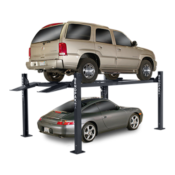
7,000 POUND CAPACITY
FOUR-POST PARKING LIFTS
MODELS:
HD-7P
HD-7W
HD-7PXW
HD-7PXN
HD-7500BL
HD-7500BLX
HD-7PBX
Keep this operation manual near the
machine at all times. Make sure that
ALL USERS read this manual.
RECEIVING
The shipment should be thoroughly inspected as soon as it
is received. The signed Bill of Lading is acknowledgement
by the shipping carrier as receipt of this product as listed
in your invoice as being in a good condition of shipment. If
any of these goods listed on this Bill of Lading are missing
or damaged, do not accept goods until the shipping carrier
makes a notation on the freight bill of the missing or dam-
aged goods. Do this for your own protection.
PLEASE READ THE ENTIRE CONTENTS OF THIS MANUAL PRIOR TO
INSTALLATION
INSTALLATION AND OPERATION YOU AGREE THAT YOU FULLY
UNDERSTAND AND COMPREHEND THE FULL CONTENTS OF THIS MANUAL.
FORWARD THIS MANUAL TO ALL OPERATORS. FAILURE TO OPER-
ATE THIS EQUIPMENT AS DIRECTED MAY CAUSE INJURY OR DEATH.
VERSION D
VERSION C
VERSION D
VERSION B
VERSION C
VERSION C
VERSION B
IMPORTANT SAFETY INSTRUCTIONS
SAVE THESE INSTRUCTIONS
AND
OPERATION.
BE SAFE
Your new lift was designed and built with safety in mind.
However, your overall safety can be increased with proper
training and thoughtful operation on the part of the operator.
DO NOT operate or repair this equipment without reading
this manual and the important safety instructions shown
inside. Keep this operation manual near the lift at all times.
Make sure that ALL USERS read and understand this
manual.
BY
PROCEEDING
Manual REV H 12-17-2013
1645 Lemonwood Dr.
Santa Paula, CA. 93060, USA
Toll Free 1-800-253-2363
Tel: 1-805-933-9970
Fax: 1-805-933-9160
www.bendpak.com
WITH
LIFT
pn# 5900041
Advertisement
Table of Contents

Related Manuals for BendPak HD-7PBX


Summary of Contents for BendPak HD-7PBX
- Page 1 VERSION D HD-7PXN VERSION B HD-7500BL VERSION C HD-7500BLX VERSION C HD-7PBX VERSION B Keep this operation manual near the machine at all times. Make sure that ALL USERS read this manual. RECEIVING BE SAFE The shipment should be thoroughly inspected as soon as it Your new lift was designed and built with safety in mind.
-
Page 2: Warranty / Serial Number Information
Our comprehensive product warranty means more than a commitment to you; it’s also a commitment to the value of your new BendPak lift. For full warranty details and to register your new lift contact your nearest BendPak dealer or visit http:/ / www.bendpak.com/ support/ warranty/... -
Page 3: Definitions Of Hazard Levels
Watch for this symbol: It Means: Hazards or unsafe and photographs, if available. Our willingness to assist in practices which may result in minor personal injury, helping you process your claim does not make BendPak product or property damage. Inc. responsible for collection of claims or replacement of... -
Page 4: Table Of Contents
TABLE OF CONTENTS Contents Page No. Warranty / Serial Number Information ..........2 Definitions of Hazard Levels . -
Page 5: Installer Operator/ Protective Equipment
I understand that BendPak lifts are designed to be installation and operation activities. installed in indoor locations only. Failure to follow... -
Page 6: Introduction
INTRODUCTION 1. Carefully remove the crating and packing 2. Check the voltage, phase and proper amperage materials. CAUTION! Be careful when cutting steel requirements for the motor shown on the motor plate. banding material as items may become loose and fall Wiring should be performed by a certified electrician only. -
Page 7: Tools Required
5” Min. Thickness / 2,500 PSI follow warnings illustrated on equipment labels. HD-7500BLX 5” Min. Thickness / 2,500 PSI HD-7PBX 5” Min. Thickness / 2,500 PSI STEP 2 ( Floor Requirements ) This lift must be installed on a solid level concrete floor with no more than 3-degrees of slope. -
Page 8: Assembly View / Description Of Parts
When removing the lift from shipping angles, pay close attention as the posts can slide and can cause injury. Prior to removing the bolts, make sure the posts are held securely by a fork lift or some other heavy lifting device. Large Windows HD-7P/W, HD-7500 SERIES (4 Pulleys) - Page 9 Large Windows HD-7PXW / PXN / PBX (4 Pulleys) SERIES ASSEMBLY VIEW Tire Stops Stiffener Offside Runway Drive Up Ramps Front Crosstube Rear Crosstube Stabilizing Cables Small Windows (2 Pulleys) Power Unit Column...
-
Page 10: Floor Plan / Specifications
FLOOR PLAN *IMPORTANT NOTE* Check Diagonal Measurements To Ensure Square Layout Diagonal Measurements Must Be Equal. MODEL HD-7P HD-7W Lifting Capacity 7,000 Lbs / 3,175 Kg 7,000 Lbs. / 3,175 Kg A Overall Width 100” / 2,540 mm 110” / 2,800 mm B Outside Length 174”... - Page 11 FLOOR PLAN *IMPORTANT NOTE* Check Diagonal Measurements To Ensure Square Layout Diagonal Measurements Must Be Equal. MODEL HD-7500BL HD-7500BLX Lifting Capacity 7,500 Lbs / 3,401 Kg 7,500 Lbs. / 3,401 Kg A Overall Width 132" / 3357 mm. 132" / 3357 mm. B Outside Length 174”...
- Page 12 FLOOR PLAN *IMPORTANT NOTE* Check Diagonal Measurements To Ensure Square Layout Diagonal Measurements Must Be Equal. MODEL HD-7PXN HD-7PXW HD-7500PBX Lifting Capacity 7,000 Lbs. / 3,175 Kg 7,000 Lbs. / 3,175 Kg 7,500 Lbs. / 3,401 Kg A Overall Width 100”...
-
Page 13: Clearances
CLEARANCES HD LIGHT DUTY APPRO AC H B. Place target on floor at column positions (NOT 1. Lift Location: Use architects plan and Engineers on column base plates) and record readings. automatic level (transit) when available to locate lift. The above shows clearances of a typical bay layout. -
Page 14: Power Unit Location
POWER UNIT LOCATION IMPORTANT NOTE: The Power Unit can be located at either “X” For the remainder of this instruction we will location shown below. It is important to illustrate the Power Unit mounted at the locate the POWERSIDE Runway (with Cyl- PASSENGER-SIDE (RIGHT) REAR Column - inder) on the SAME SIDE as the power unit TOP ILLUSTRATION. -
Page 15: Step 3 / Column And Cross Tube Installation
A maximum shim thickness of 2” is possible by ordering optional shim plates. Contact Fig 3.5 your authorized BendPak Distributor for ordering informa- tion. 3. Lay the columns down, and slide the Cross Tubes into the Columns (making sure the Plastic Slide Blocks are still in position). - Page 16 Install the Column TOP CAPS using the M16 x 2 nuts Fig 3.8 and M8 Hex Bolts, nuts & washers. Install the nut on each Safety Ladder until 1” of threads are exposed and the Ladder is raised at least 1/2” off of the base of the Col- umn.
-
Page 17: Step 4 / Raising The Cross Tubes
STEP 4 ( Raising The Cross Tubes ) Before proceeding, it will be necessary to first raise the Cross Tubes off the ground to facilitate Cable routing and final assembly. DANGER! Fig 4.3 Be careful not to disturb the Columns and Cross Tubes as they may tip over causing personal injury or harm The Columns and Cross Tubes will now be in position IMPORTANT NOTE ! -
Page 18: Step 5 / Powerside Runway Installation
STEP 5 Fig 5.4 ( Powerside Runway Installation ) 1. Locate the Powerside Runway easily identified by the Cylinder and Sheave roller mounting structures welded on the underside. The Powerside Runway will be positioned on the side of the lift where the power unit is installed. (See Fig. -
Page 19: Cable Routing Information
Cable Routing Diagrams Please review the following diagrams and Cable List. Install Lifting Cables “C” and “D” in the upper grooves of the Sheaves first. - Page 20 Cable Routing Diagrams Please review the following diagrams and Cable List. Install Lifting Cables “C” and “D” in the upper grooves of the Sheaves first. Note: Cable views are from below, looking up. Cable Identification List Please review the following Cable List. Identify each Cable prior to installation. Model Part # Description...
-
Page 21: Step 7 / Sheave Installation
STEP 7 ( Sheave Installation ) 1. Inspect Cables to ensure proper lengths. All Cables DANGER! should have ID tags showing proper Cable lengths. Failure to route Lifting Cables as described may lead to 2. In order to install the Cables it is necessary to first serious personal injury and/or death to operator or by- extend the Hydraulic Cylinder. -
Page 22: Step 9 / Power Unit Installation
STEP 9 Fig 8.3 ( Power Unit Installation ) NOTE: For HD-7PXW/PXN models refer to Page 23, Fig. 9.2 for Power Unit / Flex Hose Configuration referred to in Steps 9 & 10. Mount the Power Unit to the Mounting Bracket using the M8 Hex Head Bolts and Nylock Nuts. - Page 23 NOTE: Models HD7PXW / PXN; Power Unit/ Flex Hose Configuration. Fig 9.2 HD-7PXW / PXN Power Unit / Flex Tube Mounting Flex Tube Vibration Dampener Flex Tube Bracket Plastic Nut Return Port 90° Air Line Compression Fitting 90° Hydraulic Fitting w O-ring Power Port Power Unit AIR TUBING...
-
Page 24: Step 10 / Routing Hydraulic Hoses
The standard Power Unit for your lift is 220 volt, 60HZ, single phase. All wiring must be performed by a certified electrician only. SEE WIRING INSTRUCTIONS AFFIXED TO MOTOR FOR PROPER WIRING INSTRUCTIONS. WARNING ! DO NOT run Power Unit with no oil. Damage to pump can occur. The Power Unit must be kept dry. - Page 25 3. For HD-7PXW/PXN models, install the Straight 6. Install the end of Flex Hose with the Straight Fitting on Hydraulic Fitting in the port at the rod end of the Cylinder. the Hydraulic Hose into the hole in the Powerside Runway For HD-7P/W models use the 90°...
-
Page 26: Step 11 / Routing Air Lines
STEP 11 ( Routing Air Lines) 1. Mount the Push Button Air Valve Assembly on to the power unit mounting bracket. The Push Button Air Valve should be positioned away from the Power Side Ramp on the “out” side of the lift for operator safety. (See Fig 11.1) Fig. -
Page 27: Safety Air Line Routing
SAFETY AIR LINE ROUTING NOTE: CUT THE PROVIDED 1/4” AIR LINE TUBING WITH A SHARP BLADE TO LENGTHS AS REQUIRED. TUBING MUST BE CUT SQUARE WITH ALL PLASTIC BURRS REMOVED. AIR TUBING ASSEMBLY: SEE PAGE 22 FOR ASSEMBLY OF AIR LINE TUBING INTO FITTING. CAUTION: REMOVING THE AIR TUBING FROM THE COMPRESSION FITTINGS WILL CAUSE DAMAGE TO THE TUBING ITSELF. - Page 28 DANGER! DO NOT PERFORM ANY MAINTENANCE OR INSTALLATION OF ANY COMPONENTS WITH OUT FIRST ENSURING THAT ELECTRICAL POWER HAS BEEN DISCONNECTED AT THE SOURCE OR PANEL AND CANNOT BE RE-ENERGIZED UNTIL ALL MAINTENANCE AND/OR INSTALLATION PROCEDURES ARE COMPLETED. IMPORTANT POWER-UNIT INSTALLATION NOTES n DO NOT run power unit with no oil.
-
Page 30: Step 12 / Power Unit Hook Up
STEP 12 STEP 13 ( Power Unit Hook Up ) ( Inspecting The Slack Safety Springs ) 1. Have a certified electrician run the power supply to motor. Refer to the data plate found on the motor for proper power supply and wire size. The following steps involve the SLACK CABLE SAFETY DEVICE and MAIN SAFETY. -
Page 31: Step 15 / Anchoring The Columns
IMPORTANT NOTE: Raise lift until the lift stops and lower until the BendPak lifts are supplied with installation Safeties engage the Top Locking Position. Adjust each instructions and concrete fasteners meeting the... -
Page 32: Step 16 / Attaching Approach Ramps / Tire Stops
STEP 16 (Attaching the Approach Ramp /Tire Stops) ALWAYS WEAR SAFETY GOGGLES. 1. Install the Front Tire Stops at the forward side of the lift. Slide the Tire Stop Pin through the Ramp and the 4. Assemble the Washers and Nuts on the anchors Tire Stop. -
Page 33: Step 17 / Leveling / Synchronizing
STEP 17 Fig 17.2 ( Leveling / Synchronizing ) 1. Using an engineer’s automatic Level (transit), locate the Level at a convenient location in the shop that allows an unobstructed view of all four corners of the runways. 2. Follow the Level manufacturer’s instructions for proper setup of the Level. -
Page 34: Step 19 / Operation Instructions
POST-INSTALLATION CHECK-OFF Lifting Points/Quick Reference Guide for Frame Engaging Lifts. n Columns properly shimmed and stable • Shall establish procedures to periodically inspect the n Anchor Bolts tightened lift in accordance with the lift manufacturer’s instructions or ANSI/ALI ALOIM-2000, American National Standard n Pivot / Sheave Pins properly attached for Automotive Lifts-Safety Requirements for Operation, n Electric power supply confirmed... - Page 35 • AVOID excessive rocking of vehicle while on lift. or if it has broken or damaged parts. Use only qualified lift service personnel and genuine BendPak parts to make • ALWAYS CLEAR AREA if vehicle is in danger of falling.
-
Page 36: Maintenance
2. Check safety locks to ensure they are in good operat- ing condition. 3. Check cables and sheaves for wear. Replace worn parts as required with genuine BendPak parts. 4. Inspect adapters for damage or excessive wear. Re- place as required with genuine BendPak parts. - Page 37 WIRE ROPE INSPECTION AND MAINTENANCE Lifting cables should be replaced every three - five years or when visible signs of damage are apparent. DO NOT USE LIFT WITH DEFECTIVE / WORN CABLES. Lifting cables should be maintained in a well-lubricated condition at all times. Wire rope is only fully protected when each wire strand is lubricated both internal and external.
-
Page 40: Step 20 / Lift Operation Safety
Safe Lift Operation Automotive and truck lifts are critical to the operation and profitability of your business. The safe use of this and other lifts in your shop is critical in preventing employee injuries and damage to customers’ vehicles. By operating lifts safely, you can ensure that your shop is profitable, productive and safe. - Page 41 DO NOT leave the controls while the lift is still in motion. DO NOT stand directly in front of the vehicle or in the bay when vehicle is being loaded or driven into position. DO NOT Go near vehicle or attempt to work on the vehicle when being raised or lowered. REMAIN CLEAR of lift when raising or lowering vehicle.
-
Page 42: Troubleshooting Guide
LIFT WILL NOT RAISE POSSIBLE CAUSE 1. Air in oil, (1,2,8,13) 2. Cylinder binding, (9) 3. Cylinder leaks internally, (9) 4. Motor run backward under pressure, (11) 5. Lowering valve leaks, (3,4,6,10,11) 6. Motor runs backwards, (7,14,11) 7. Pump damaged, (10,11) 8. - Page 43 MOTOR WILL NOT RUN POSSIBLE CAUSE Fuse blown, (5,2,1,3,4) Limit switch burned out, (1,2,3,4) Microswitch burned out, (1,2,3,4) Motor burned out, (1,2,3,4,6) Voltage to motor incorrect, (2,1,8) REMEDY INSTRUCTION Check for correct voltage ......Compare supply voltage with voltage on motor name tag.
- Page 44 WILL NOT RAISE LOADED LIFT POSSIBLE CAUSE 1. Air in oil, (1,2,3,4) 2. Cylinder binding, (5) 3. Cylinder leaks internally, (5) 4. Lift overloaded, (6,5) 5. Lowering valve leaks, (7,8,1,5,9) 6. Motor runs backwards, (10,12,9) 7. Pump damaged, (5,9) 8. Pump won’t prime, (1,2,3,4,5,11,9) 9.
- Page 45 LIFT WILL NOT STAY UP POSSIBLE CAUSE 1. Air in oil, (1,2,3) 5. Leaking fittings, (8) 2. Check valve leaks, (6) 4. Lowering valve leaks, (4,5,1,7,6) 3. Cylinders leak internally, (7) REMEDY INSTRUCTION 1. Check oil level ........The oil level should be up to the bleed screw in the reservoir with the lift all the way down.
-
Page 46: Grease Port Locations
Grease Port / Lubrication Locations Lubricate Once A Week Torque Recommendations VALUES ARE STATED IN FOOT POUNDS (ft-lb) SAE 0-1-2 SAE Grade 5 SAE Grade 8 SOCKET HEAD CAP SCREW CLASS 4.8 CLASS 8.8 CLASS 10.9 CLASS 12.9 Bolt Size Bolt Size (SAE) (Metric) -
Page 47: Maintenance Records
MAINTENANCE RECORDS ____________________________________________________________________ ____________________________________________________________________ ____________________________________________________________________ ____________________________________________________________________ ____________________________________________________________________ ____________________________________________________________________ ____________________________________________________________________ ____________________________________________________________________ ____________________________________________________________________ ____________________________________________________________________ ____________________________________________________________________ ____________________________________________________________________ ____________________________________________________________________ ____________________________________________________________________ ____________________________________________________________________ ____________________________________________________________________ ____________________________________________________________________ ____________________________________________________________________ ____________________________________________________________________ ____________________________________________________________________... - Page 67 This page intentionally left blank.
- Page 68 For Parts Or Service Contact: BendPak Inc. / Ranger Products 1645 Lemonwood Dr. Santa Paula, CA. 93060 Tel: 1-805-933-9970 Toll Free: 1-800-253-2363 Fax: 1-805-933-9160 www.bendpak.com pn# 5900041...
Need help?
Do you have a question about the HD-7PBX and is the answer not in the manual?
Questions and answers